
User Manual
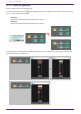
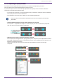
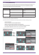
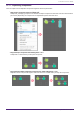
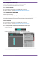
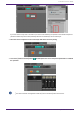
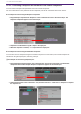
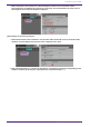
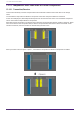
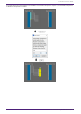
Table Of Contents
- ProVisionaire Design
- Contents
- 1. Introduction
- 2. Screen structure
- 3. The basics of using ProVisionaire Design
- 4. Menu bars and toolbar
- 5. Shortcut keys
- 6. List of alerts
- 7. "Project" sheet
- 8. "Tuning" sheet
- 9. Online and synchronization
- 10. Dialog boxes
- 10.1. Startup dialog box
- 10.2. "Go Online- From Devices" dialog box
- 10.3. "Protect File" dialog box
- 10.4. "Project Information" dialog box
- 10.5. "Print" dialog box
- 10.6. "File Storage" dialog box
- 10.7. "Network Setup" dialog box
- 10.8. "IP Settings" dialog box
- 10.9. "IP Address" dialog box
- 10.10. "Auto-Assign IP Addresses" dialog box
- 10.11. "Match Devices by IP Address" dialog box
- 10.12. "Device Information" dialog box
- 10.13. "Update Firmware" dialog box
- 10.14. "Initialize" dialog box
- 10.15. "Word Clock" dialog box
- 10.16. "Protect Devices" dialog box
- 10.17. "Clock" dialog box
- 10.18. "Daylight Saving Time" dialog box
- 10.19. "GPI Calibration" dialog box
- 10.20. "Get Log from Devices" dialog box
- 10.21. "RM Series Settings" > "Sign up" dialog box
- 10.22. "RM Series Settings" > "Login" dialog box
- 10.23. "RM Series Settings" > "Password Settings" dialog box
- 10.24. "RM Series Settings" > "Enable SCP remote control access" dialog box
- 10.25. "Linked Presets Manager" dialog box
- 10.26. "Store Linked Preset" dialog box
- 10.27. Port Label Dialog
- 11. Context menus
- 12. Common operations for device sheets
- 13. Audio Processors: DME7
- 13.1. Overview
- 13.2. "Project" sheet
- 13.3. Device sheet screen configuration
- 13.4. Basic use of ProVisonaire Designer
- 13.5. Tool buttons
- 13.6. "Components" area
- 13.7. Design sheet
- 13.8. Design sheet: Audio layer
- 13.9. Design sheet: Control layer
- 13.10. Components other than audio or control components
- 13.11. “Parameter Sets” area
- 13.12. “Properties” area
- 13.13. "Parameters" area
- 13.14. Context Menu
- 13.15. Dialog box
- 13.16. Message List
- 14. Audio Processor MRX7-D
- 14.1. Overview
- 14.2. Project Sheet
- 14.3. Device Sheet Screen Configuration
- 14.4. Basic Use
- 14.5. Tool Buttons
- 14.6. Components Area
- 14.7. Design Sheet
- 14.8. Non-Audio Components
- 14.9. Parameter Sets Area
- 14.10. Presets Area
- 14.11. Parameter Link Group Area
- 14.12. Gang Edit Group Area
- 14.13. Properties Area
- 14.14. Parameters Area
- 14.15. Context Menu
- 14.16. Dialog
- 14.17. Component Editor
- 14.18. Alert List
- 14.19. Flow of Paging Configuration
- 15. Audio Processors: MTX5-D/MTX3
- 15.1. Overview
- 15.2. "Project" sheet
- 15.3. Device sheet screen configuration
- 15.4. Tool buttons
- 15.5. "Presets" area
- 15.6. Context menus
- 15.7. Dialog box
- 15.8. Alert list
- 15.9. Component editors
- 15.9.1. "Analog In" component editor
- 15.9.2. “MY4-AEC” component editor
- 15.9.3. "Input CH" component editor
- 15.9.4. "Insert" component editor
- 15.9.5. "Zone" component editor
- 15.9.6. "Output CH" component editor
- 15.9.7. "Pilot Tone" component editor
- 15.9.8. "Analog Out" component editor
- 15.9.9. "Slot Out" component editor
- 15.9.10. "DCA Groups"/"Mute Groups" component editor
- 15.10. Workflow for paging settings
- 16. MTX I/O Expanders: EXi8 / Exo8
- 17. Power Amplifiers: PC-series
- 18. Power Amplifiers: XMV-series
- 19. I/O Interface: Rio3224-D2 / Rio1608-D2
- 20. I/O Interface: Tio1608-D / Tio1608-D2
- 21. I/O Interface: RSio64-D
- 22. Powered Speakers: VXL1-16P
- 23. Microphones: PGM1
- 24. Microphones: RM-CG
- 25. Microphones: RM-TT
- 26. External Device: Speakers
- 27. DCP
- 28. Wall-mount Controller: MCP1
- 29. YDIF
- 30. Settings for controlling devices across subnets
-

13.8. Design sheet: Audio layer
This layer enables you to place audio components to create a configuration.
You can control audio signals by wiring between audio components.
13.8.1. Audio Component
For more information on how to use the component editor, refer to Chapter 12.
For details on components, refer to the "ProVisionaire Design DME7 Component Guide" .
13.9. Design sheet: Control layer
This layer handles control signals.
You can manipulate control signals by wiring between the control components or audio components.
Control components can be manipulated via changes in parameters or meters for the audio components. Audio
components can be manipulated via changes in parameters for the control components.
You can also place snapshots in the Control layer, which can be treated as part of the configuration.
Control Component
For more information on how to use the component editor, refer to Chapter 12.
For details on components, refer to the "ProVisionaire Design DME7 Component Guide" .
13.9.1. Using the audio component parameters in the Control layer
1. Select the Audio layer.
2. Select the “Parameters” area, and then select the audio component in the sheet.
In the Control PINs column, add a check mark to the check box for the desired parameters. The audio
component is placed in the Control layer, too.
13. Audio Processors: DME7
134 | ProVisionaire Design V1.2 User Guide