
User Manual
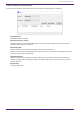
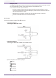
Table Of Contents
- ProVisionaire Design
- Contents
- 1. Introduction
- 2. Screen structure
- 3. The basics of using ProVisionaire Design
- 4. Menu bars and toolbar
- 5. Shortcut keys
- 6. List of alerts
- 7. "Project" sheet
- 8. "Tuning" sheet
- 9. Online and synchronization
- 10. Dialog boxes
- 10.1. Startup dialog box
- 10.2. "Go Online- From Devices" dialog box
- 10.3. "Protect File" dialog box
- 10.4. "Project Information" dialog box
- 10.5. "Print" dialog box
- 10.6. "File Storage" dialog box
- 10.7. "Network Setup" dialog box
- 10.8. "IP Settings" dialog box
- 10.9. "IP Address" dialog box
- 10.10. "Auto-Assign IP Addresses" dialog box
- 10.11. "Match Devices by IP Address" dialog box
- 10.12. "Device Information" dialog box
- 10.13. "Update Firmware" dialog box
- 10.14. "Initialize" dialog box
- 10.15. "Word Clock" dialog box
- 10.16. "Protect Devices" dialog box
- 10.17. "Clock" dialog box
- 10.18. "Daylight Saving Time" dialog box
- 10.19. "GPI Calibration" dialog box
- 10.20. "Get Log from Devices" dialog box
- 10.21. "RM Series Settings" > "Sign up" dialog box
- 10.22. "RM Series Settings" > "Login" dialog box
- 10.23. "RM Series Settings" > "Password Settings" dialog box
- 10.24. "RM Series Settings" > "Enable SCP remote control access" dialog box
- 10.25. "Linked Presets Manager" dialog box
- 10.26. "Store Linked Preset" dialog box
- 10.27. Port Label Dialog
- 11. Context menus
- 12. Common operations for device sheets
- 13. Audio Processors: DME7
- 13.1. Overview
- 13.2. "Project" sheet
- 13.3. Device sheet screen configuration
- 13.4. Basic use of ProVisonaire Designer
- 13.5. Tool buttons
- 13.6. "Components" area
- 13.7. Design sheet
- 13.8. Design sheet: Audio layer
- 13.9. Design sheet: Control layer
- 13.10. Components other than audio or control components
- 13.11. “Parameter Sets” area
- 13.12. “Properties” area
- 13.13. "Parameters" area
- 13.14. Context Menu
- 13.15. Dialog box
- 13.16. Message List
- 14. Audio Processor MRX7-D
- 14.1. Overview
- 14.2. Project Sheet
- 14.3. Device Sheet Screen Configuration
- 14.4. Basic Use
- 14.5. Tool Buttons
- 14.6. Components Area
- 14.7. Design Sheet
- 14.8. Non-Audio Components
- 14.9. Parameter Sets Area
- 14.10. Presets Area
- 14.11. Parameter Link Group Area
- 14.12. Gang Edit Group Area
- 14.13. Properties Area
- 14.14. Parameters Area
- 14.15. Context Menu
- 14.16. Dialog
- 14.17. Component Editor
- 14.18. Alert List
- 14.19. Flow of Paging Configuration
- 15. Audio Processors: MTX5-D/MTX3
- 15.1. Overview
- 15.2. "Project" sheet
- 15.3. Device sheet screen configuration
- 15.4. Tool buttons
- 15.5. "Presets" area
- 15.6. Context menus
- 15.7. Dialog box
- 15.8. Alert list
- 15.9. Component editors
- 15.9.1. "Analog In" component editor
- 15.9.2. “MY4-AEC” component editor
- 15.9.3. "Input CH" component editor
- 15.9.4. "Insert" component editor
- 15.9.5. "Zone" component editor
- 15.9.6. "Output CH" component editor
- 15.9.7. "Pilot Tone" component editor
- 15.9.8. "Analog Out" component editor
- 15.9.9. "Slot Out" component editor
- 15.9.10. "DCA Groups"/"Mute Groups" component editor
- 15.10. Workflow for paging settings
- 16. MTX I/O Expanders: EXi8 / Exo8
- 17. Power Amplifiers: PC-series
- 18. Power Amplifiers: XMV-series
- 19. I/O Interface: Rio3224-D2 / Rio1608-D2
- 20. I/O Interface: Tio1608-D / Tio1608-D2
- 21. I/O Interface: RSio64-D
- 22. Powered Speakers: VXL1-16P
- 23. Microphones: PGM1
- 24. Microphones: RM-CG
- 25. Microphones: RM-TT
- 26. External Device: Speakers
- 27. DCP
- 28. Wall-mount Controller: MCP1
- 29. YDIF
- 30. Settings for controlling devices across subnets
-

13.15.4. "GPI" dialog box
To open this dialog box, click [GPI] from the [Tools] button in the “Device” sheet.
GPI stands for General Purpose Interface. By using the GPI input/output, you can remotely control the DME7 via
custom-made controllers or external devices. A controller that is connected to the GPI input connector can be
used to switch snapshots on the DME7 or to control the parameters of components.
Display devices such as LEDs and lamps or external control equipment made by other manufacturers can be
connected to the GPI output connector, letting you control the external device according to the state of presets
or parameters.
For hardware-related details such as how to connect the [GPI] connector, refer to the owner’s guide of each unit.
There are two methods to set up the GPI input.
・ Using the “GPI Input” dialog box, which you can access from the [Tools] button in the “Device” sheet.
Use this method to execute a single function via a single port input.
・Adding the GPI Input component to the Control layer in the “Device” sheet, and using the editor to set it up.
Use this method if you wish to control multiple parameters or functions simultaneously via a single input port, or
if you wish to manipulate a complex operation by combining multiple control components.
* For GPI input, both the settings in the dialog box and the settings by the GPI Input component in the Control
layer will be executed simultaneously.
There are two methods to set up the GPI output.
・Using the “GPI Output” dialog box, which you can access from the [Tools] buttons in the “Device” sheet.
Use this method to output a signal via a single output port based on a single operation as the factor.
・Adding the GPI Output component to the Control layer in the “Device” sheet, and using the editor to set it up.
Use this method if you wish to output a signal via a single output port based on multiple operations as the factor,
or if you wish to execute a complex operation by combining multiple control components.
* The Output Port Type setting is linked between this dialog box and the GPI Output component in the Control
layer.
■ Operations applied to both the “GPI Input” and “GPI Output” dialog boxes
•
[Clear All] button
Initializes the settings of all ports.
•
[Port] select buttons
Click this button to open the “Settings” dialog box.
•
[OK] button
Applies the setting and closes the dialog box.
13. Audio Processors: DME7
ProVisionaire Design V1.2 User Guide | 165