
User Manual
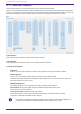
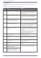
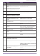
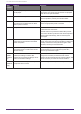
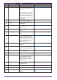
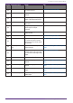
Table Of Contents
- ProVisionaire Design
- Contents
- 1. Introduction
- 2. Screen structure
- 3. The basics of using ProVisionaire Design
- 4. Menu bars and toolbar
- 5. Shortcut keys
- 6. List of alerts
- 7. "Project" sheet
- 8. "Tuning" sheet
- 9. Online and synchronization
- 10. Dialog boxes
- 10.1. Startup dialog box
- 10.2. "Go Online- From Devices" dialog box
- 10.3. "Protect File" dialog box
- 10.4. "Project Information" dialog box
- 10.5. "Print" dialog box
- 10.6. "File Storage" dialog box
- 10.7. "Network Setup" dialog box
- 10.8. "IP Settings" dialog box
- 10.9. "IP Address" dialog box
- 10.10. "Auto-Assign IP Addresses" dialog box
- 10.11. "Match Devices by IP Address" dialog box
- 10.12. "Device Information" dialog box
- 10.13. "Update Firmware" dialog box
- 10.14. "Initialize" dialog box
- 10.15. "Word Clock" dialog box
- 10.16. "Protect Devices" dialog box
- 10.17. "Clock" dialog box
- 10.18. "Daylight Saving Time" dialog box
- 10.19. "GPI Calibration" dialog box
- 10.20. "Get Log from Devices" dialog box
- 10.21. "RM Series Settings" > "Sign up" dialog box
- 10.22. "RM Series Settings" > "Login" dialog box
- 10.23. "RM Series Settings" > "Password Settings" dialog box
- 10.24. "RM Series Settings" > "Enable SCP remote control access" dialog box
- 10.25. "Linked Presets Manager" dialog box
- 10.26. "Store Linked Preset" dialog box
- 10.27. Port Label Dialog
- 11. Context menus
- 12. Common operations for device sheets
- 13. Audio Processors: DME7
- 13.1. Overview
- 13.2. "Project" sheet
- 13.3. Device sheet screen configuration
- 13.4. Basic use of ProVisonaire Designer
- 13.5. Tool buttons
- 13.6. "Components" area
- 13.7. Design sheet
- 13.8. Design sheet: Audio layer
- 13.9. Design sheet: Control layer
- 13.10. Components other than audio or control components
- 13.11. “Parameter Sets” area
- 13.12. “Properties” area
- 13.13. "Parameters" area
- 13.14. Context Menu
- 13.15. Dialog box
- 13.16. Message List
- 14. Audio Processor MRX7-D
- 14.1. Overview
- 14.2. Project Sheet
- 14.3. Device Sheet Screen Configuration
- 14.4. Basic Use
- 14.5. Tool Buttons
- 14.6. Components Area
- 14.7. Design Sheet
- 14.8. Non-Audio Components
- 14.9. Parameter Sets Area
- 14.10. Presets Area
- 14.11. Parameter Link Group Area
- 14.12. Gang Edit Group Area
- 14.13. Properties Area
- 14.14. Parameters Area
- 14.15. Context Menu
- 14.16. Dialog
- 14.17. Component Editor
- 14.18. Alert List
- 14.19. Flow of Paging Configuration
- 15. Audio Processors: MTX5-D/MTX3
- 15.1. Overview
- 15.2. "Project" sheet
- 15.3. Device sheet screen configuration
- 15.4. Tool buttons
- 15.5. "Presets" area
- 15.6. Context menus
- 15.7. Dialog box
- 15.8. Alert list
- 15.9. Component editors
- 15.9.1. "Analog In" component editor
- 15.9.2. “MY4-AEC” component editor
- 15.9.3. "Input CH" component editor
- 15.9.4. "Insert" component editor
- 15.9.5. "Zone" component editor
- 15.9.6. "Output CH" component editor
- 15.9.7. "Pilot Tone" component editor
- 15.9.8. "Analog Out" component editor
- 15.9.9. "Slot Out" component editor
- 15.9.10. "DCA Groups"/"Mute Groups" component editor
- 15.10. Workflow for paging settings
- 16. MTX I/O Expanders: EXi8 / Exo8
- 17. Power Amplifiers: PC-series
- 18. Power Amplifiers: XMV-series
- 19. I/O Interface: Rio3224-D2 / Rio1608-D2
- 20. I/O Interface: Tio1608-D / Tio1608-D2
- 21. I/O Interface: RSio64-D
- 22. Powered Speakers: VXL1-16P
- 23. Microphones: PGM1
- 24. Microphones: RM-CG
- 25. Microphones: RM-TT
- 26. External Device: Speakers
- 27. DCP
- 28. Wall-mount Controller: MCP1
- 29. YDIF
- 30. Settings for controlling devices across subnets
-

15.8. Alert list
The alerts generated by MRX7-D/MTX5-D/MTX3 units, and their significance and the appropriate actions, are
listed below.
If the problem is not solved, please contact your Yamaha dealer.
Alert
number
Meaning Response
01–09 The device has not started up correctly. Turn the power off, then turn on after waiting at least 6
seconds. If this does not solve the problem, please
initialize the memory. Should this also fails, contact
your Yamaha dealer.
10 The internal backup battery has been
completely exhausted or is not installed.
When you turn off the power, the current settings will
be lost, and will return to the default values. Please
stop use immediately, and contact your Yamaha
dealer.
11 The internal backup battery has run
extremely low, and it is possible that the
internal memory has been cleared.
When you turn off the power, the current settings will
be lost, and will return to the default values. Please
stop use immediately, and contact your Yamaha
dealer.
12 The internal backup battery has only a
small amount of power remaining.
This does not affect the operation of the device.
However, if you continue using the device, the settings
may be lost and reset to the default values. Contact
your Yamaha dealer as soon as possible.
13 A problem has occurred with the internal
clock, and it has been initialized (January 1,
2000, 0:00).
If this occurs each time you turn on the power, it is
possible that the internal backup battery has run down
or that the device has malfunctioned. Contact your
Yamaha dealer.
If this occurs only once, an abnormality was detected
with the clock setting and it was initialized; use
ProVisionaire Design to set the time.
14 The current preset saved in internal
memory has been lost.
Recall the preset. If this does not solve the problem,
contact your Yamaha dealer.
15 The settings saved in internal memory have
been lost.
Either the internal backup battery has run low, or the
device has malfunctioned. Contact your Yamaha
dealer.
20 An unsupported Mini-YGDAI card is inserted
in the slot, or the inserted Mini-YGDAI card
has malfunctioned.
Replace the card with a supported Mini-YGDAI card or
check that the supported Mini-YGDAI card is working
correctly in another Host.
21 The word clock leader has become
unlocked.
Make sure that the word clock signal is being input
correctly.
22 The digital signal being input to the [YDIF
IN] connector is not synchronized to the
word clock of this device.
Make sure that YDIF cables are properly connected.
Use cables that meet the required specifications.
23 The digital signal being input to the [YDIF
IN] connector is not continuously
synchronized to the word clock of this
device.
15. Audio Processors: MTX5-D/MTX3
254 | ProVisionaire Design V1.2 User Guide