
User Manual
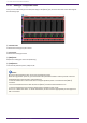
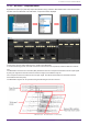
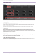


Table Of Contents
- ProVisionaire Design
- Contents
- 1. Introduction
- 2. Screen structure
- 3. The basics of using ProVisionaire Design
- 4. Menu bars and toolbar
- 5. Shortcut keys
- 6. List of alerts
- 7. "Project" sheet
- 8. "Tuning" sheet
- 9. Online and synchronization
- 10. Dialog boxes
- 10.1. Startup dialog box
- 10.2. "Go Online- From Devices" dialog box
- 10.3. "Protect File" dialog box
- 10.4. "Project Information" dialog box
- 10.5. "Print" dialog box
- 10.6. "File Storage" dialog box
- 10.7. "Network Setup" dialog box
- 10.8. "IP Settings" dialog box
- 10.9. "IP Address" dialog box
- 10.10. "Auto-Assign IP Addresses" dialog box
- 10.11. "Match Devices by IP Address" dialog box
- 10.12. "Device Information" dialog box
- 10.13. "Update Firmware" dialog box
- 10.14. "Initialize" dialog box
- 10.15. "Word Clock" dialog box
- 10.16. "Protect Devices" dialog box
- 10.17. "Clock" dialog box
- 10.18. "Daylight Saving Time" dialog box
- 10.19. "GPI Calibration" dialog box
- 10.20. "Get Log from Devices" dialog box
- 10.21. "RM Series Settings" > "Sign up" dialog box
- 10.22. "RM Series Settings" > "Login" dialog box
- 10.23. "RM Series Settings" > "Password Settings" dialog box
- 10.24. "RM Series Settings" > "Enable SCP remote control access" dialog box
- 10.25. "Linked Presets Manager" dialog box
- 10.26. "Store Linked Preset" dialog box
- 10.27. Port Label Dialog
- 11. Context menus
- 12. Common operations for device sheets
- 13. Audio Processors: DME7
- 13.1. Overview
- 13.2. "Project" sheet
- 13.3. Device sheet screen configuration
- 13.4. Basic use of ProVisonaire Designer
- 13.5. Tool buttons
- 13.6. "Components" area
- 13.7. Design sheet
- 13.8. Design sheet: Audio layer
- 13.9. Design sheet: Control layer
- 13.10. Components other than audio or control components
- 13.11. “Parameter Sets” area
- 13.12. “Properties” area
- 13.13. "Parameters" area
- 13.14. Context Menu
- 13.15. Dialog box
- 13.16. Message List
- 14. Audio Processor MRX7-D
- 14.1. Overview
- 14.2. Project Sheet
- 14.3. Device Sheet Screen Configuration
- 14.4. Basic Use
- 14.5. Tool Buttons
- 14.6. Components Area
- 14.7. Design Sheet
- 14.8. Non-Audio Components
- 14.9. Parameter Sets Area
- 14.10. Presets Area
- 14.11. Parameter Link Group Area
- 14.12. Gang Edit Group Area
- 14.13. Properties Area
- 14.14. Parameters Area
- 14.15. Context Menu
- 14.16. Dialog
- 14.17. Component Editor
- 14.18. Alert List
- 14.19. Flow of Paging Configuration
- 15. Audio Processors: MTX5-D/MTX3
- 15.1. Overview
- 15.2. "Project" sheet
- 15.3. Device sheet screen configuration
- 15.4. Tool buttons
- 15.5. "Presets" area
- 15.6. Context menus
- 15.7. Dialog box
- 15.8. Alert list
- 15.9. Component editors
- 15.9.1. "Analog In" component editor
- 15.9.2. “MY4-AEC” component editor
- 15.9.3. "Input CH" component editor
- 15.9.4. "Insert" component editor
- 15.9.5. "Zone" component editor
- 15.9.6. "Output CH" component editor
- 15.9.7. "Pilot Tone" component editor
- 15.9.8. "Analog Out" component editor
- 15.9.9. "Slot Out" component editor
- 15.9.10. "DCA Groups"/"Mute Groups" component editor
- 15.10. Workflow for paging settings
- 16. MTX I/O Expanders: EXi8 / Exo8
- 17. Power Amplifiers: PC-series
- 18. Power Amplifiers: XMV-series
- 19. I/O Interface: Rio3224-D2 / Rio1608-D2
- 20. I/O Interface: Tio1608-D / Tio1608-D2
- 21. I/O Interface: RSio64-D
- 22. Powered Speakers: VXL1-16P
- 23. Microphones: PGM1
- 24. Microphones: RM-CG
- 25. Microphones: RM-TT
- 26. External Device: Speakers
- 27. DCP
- 28. Wall-mount Controller: MCP1
- 29. YDIF
- 30. Settings for controlling devices across subnets
-

■ “Mic” screen
When using a mic equipped with a PTT (Push To Talk) switch, a small amount of noise may be heard while the
PTT switch is off. If this noise is input to the AEC, the AEC will mistakenly learn the noise, causing an echo when
the PTT switch is turned on to resume speaking. In this screen you can make settings and specify the type of
mic to prevent this from occurring.
① PTT [ON] button
If this is on, and the input level from the local mic (Near-end Mic) falls below the value specified in PTT
Threshold, the system will determine that the PTT switch of the local mic has been turned off, and will stop AEC
learning. We recommend
that you leave this on.
② Mic In. meter
This indicates the level of the signal that is input from the local mic (Near-end Mic). This meter will also indicate
the level of the noise that occurs when the PTT button of the mic is off.
③ [PTT Threshold] knob
This knob sets the reference level for AEC learning. If the PTT [ON] button is on, AEC learning will stop when the
input signal to the local mic (Near-end Mic) falls below this level; learning will resume when the input signal
exceeds this level.
The Mic In. meter indicates the level of the input signal.
④ [Mic. Type] list box
Specify the type of mic that is connected.
Choose “Fixed” for an environment in which the distance between the mic and speaker is fixed, or “Moving” for
an environment in which this distance changes, such as when a hand mic is used. Even in an environment in
which the distance between the mic and speaker is fixed, choose “Moving” if the echo is obtrusive.
15. Audio Processors: MTX5-D/MTX3
ProVisionaire Design V1.2 User Guide | 265