
User Manual
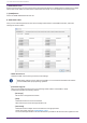
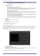
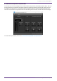

Table Of Contents
- ProVisionaire Design
- Contents
- 1. Introduction
- 2. Screen structure
- 3. The basics of using ProVisionaire Design
- 4. Menu bars and toolbar
- 5. Shortcut keys
- 6. List of alerts
- 7. "Project" sheet
- 8. "Tuning" sheet
- 9. Online and synchronization
- 10. Dialog boxes
- 10.1. Startup dialog box
- 10.2. "Go Online- From Devices" dialog box
- 10.3. "Protect File" dialog box
- 10.4. "Project Information" dialog box
- 10.5. "Print" dialog box
- 10.6. "File Storage" dialog box
- 10.7. "Network Setup" dialog box
- 10.8. "IP Settings" dialog box
- 10.9. "IP Address" dialog box
- 10.10. "Auto-Assign IP Addresses" dialog box
- 10.11. "Match Devices by IP Address" dialog box
- 10.12. "Device Information" dialog box
- 10.13. "Update Firmware" dialog box
- 10.14. "Initialize" dialog box
- 10.15. "Word Clock" dialog box
- 10.16. "Protect Devices" dialog box
- 10.17. "Clock" dialog box
- 10.18. "Daylight Saving Time" dialog box
- 10.19. "GPI Calibration" dialog box
- 10.20. "Get Log from Devices" dialog box
- 10.21. "RM Series Settings" > "Sign up" dialog box
- 10.22. "RM Series Settings" > "Login" dialog box
- 10.23. "RM Series Settings" > "Password Settings" dialog box
- 10.24. "RM Series Settings" > "Enable SCP remote control access" dialog box
- 10.25. "Linked Presets Manager" dialog box
- 10.26. "Store Linked Preset" dialog box
- 10.27. Port Label Dialog
- 11. Context menus
- 12. Common operations for device sheets
- 13. Audio Processors: DME7
- 13.1. Overview
- 13.2. "Project" sheet
- 13.3. Device sheet screen configuration
- 13.4. Basic use of ProVisonaire Designer
- 13.5. Tool buttons
- 13.6. "Components" area
- 13.7. Design sheet
- 13.8. Design sheet: Audio layer
- 13.9. Design sheet: Control layer
- 13.10. Components other than audio or control components
- 13.11. “Parameter Sets” area
- 13.12. “Properties” area
- 13.13. "Parameters" area
- 13.14. Context Menu
- 13.15. Dialog box
- 13.16. Message List
- 14. Audio Processor MRX7-D
- 14.1. Overview
- 14.2. Project Sheet
- 14.3. Device Sheet Screen Configuration
- 14.4. Basic Use
- 14.5. Tool Buttons
- 14.6. Components Area
- 14.7. Design Sheet
- 14.8. Non-Audio Components
- 14.9. Parameter Sets Area
- 14.10. Presets Area
- 14.11. Parameter Link Group Area
- 14.12. Gang Edit Group Area
- 14.13. Properties Area
- 14.14. Parameters Area
- 14.15. Context Menu
- 14.16. Dialog
- 14.17. Component Editor
- 14.18. Alert List
- 14.19. Flow of Paging Configuration
- 15. Audio Processors: MTX5-D/MTX3
- 15.1. Overview
- 15.2. "Project" sheet
- 15.3. Device sheet screen configuration
- 15.4. Tool buttons
- 15.5. "Presets" area
- 15.6. Context menus
- 15.7. Dialog box
- 15.8. Alert list
- 15.9. Component editors
- 15.9.1. "Analog In" component editor
- 15.9.2. “MY4-AEC” component editor
- 15.9.3. "Input CH" component editor
- 15.9.4. "Insert" component editor
- 15.9.5. "Zone" component editor
- 15.9.6. "Output CH" component editor
- 15.9.7. "Pilot Tone" component editor
- 15.9.8. "Analog Out" component editor
- 15.9.9. "Slot Out" component editor
- 15.9.10. "DCA Groups"/"Mute Groups" component editor
- 15.10. Workflow for paging settings
- 16. MTX I/O Expanders: EXi8 / Exo8
- 17. Power Amplifiers: PC-series
- 18. Power Amplifiers: XMV-series
- 19. I/O Interface: Rio3224-D2 / Rio1608-D2
- 20. I/O Interface: Tio1608-D / Tio1608-D2
- 21. I/O Interface: RSio64-D
- 22. Powered Speakers: VXL1-16P
- 23. Microphones: PGM1
- 24. Microphones: RM-CG
- 25. Microphones: RM-TT
- 26. External Device: Speakers
- 27. DCP
- 28. Wall-mount Controller: MCP1
- 29. YDIF
- 30. Settings for controlling devices across subnets
-

◦ [Stop broadcast except for 1st Priority PGM1] option button
If this is selected, paging broadcast will be possible only for the 1st Priority PGM1 when the MTX is
in emergency mode.
• Paging Device Group
◦ [Opening Chime]/[Closing Chime] check boxes
If these check boxes are selected, you can make settings for the opening chime and/ or closing
chime. Click the button at right to specify the chime file that will play. This setting is shared by the
PGM1 (Paging Device Group) units that are connected to the same MTX.
◦ [Maximum paging duration] list box
Selects the time after PTT is turned on until it is automatically turned off. If a message is being
played back, it will not turn off even if the specified time is exceeded. This setting is shared by the
PGM1 units that are connected to the same MTX.
◦
[The scheduler’s paging events are broadcast with higher priority than PGM1. Paging events have
a lower priority than 1st Priority PGM1.] check box
If this check box is selected, the priority order will be “1st Priority PGM1 > events > normal PGM1.”
If this check box is cleared, the priority order will be “1st Priority PGM1 > normal PGM1 > events.”
•
[OK] button
Saves the settings and closes the dialog box.
•
[Cancel] button
Discards the settings and closes the dialog box.
■ "PRIORITY DUCKER" component editor
You can make ducker settings.
The ducker is a function that temporarily reduces the input from one channel when an audio signal is input to
another specified input channel, allowing the audio from the specified channel to be heard clearly. The priority
order is as follows: “PRIORITY SOURCE” of the “1st PRIORITY” > “PRIORITY SOURCE” of the “2nd PRIORITY” >
MATRIX Out signal.
•
[PRIORITY SOURCE] list
Selects the input signal for the ducker.
Select [ANC Bus] if you want the mixed signal to be the high-priority audio. The mix of audio signals to the
ANC bus can be created in the "Matrix Mixer" component editor.
For details about other parameters, refer to the "ProVisionaire Design DME7 Component Guide" .
15. Audio Processors: MTX5-D/MTX3
274 | ProVisionaire Design V1.2 User Guide