
User Manual
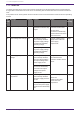
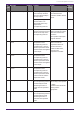
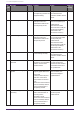
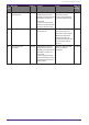
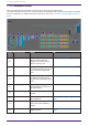
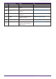
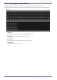
Table Of Contents
- ProVisionaire Design
- Contents
- 1. Introduction
- 2. Screen structure
- 3. The basics of using ProVisionaire Design
- 4. Menu bars and toolbar
- 5. Shortcut keys
- 6. List of alerts
- 7. "Project" sheet
- 8. "Tuning" sheet
- 9. Online and synchronization
- 10. Dialog boxes
- 10.1. Startup dialog box
- 10.2. "Go Online- From Devices" dialog box
- 10.3. "Protect File" dialog box
- 10.4. "Project Information" dialog box
- 10.5. "Print" dialog box
- 10.6. "File Storage" dialog box
- 10.7. "Network Setup" dialog box
- 10.8. "IP Settings" dialog box
- 10.9. "IP Address" dialog box
- 10.10. "Auto-Assign IP Addresses" dialog box
- 10.11. "Match Devices by IP Address" dialog box
- 10.12. "Device Information" dialog box
- 10.13. "Update Firmware" dialog box
- 10.14. "Initialize" dialog box
- 10.15. "Word Clock" dialog box
- 10.16. "Protect Devices" dialog box
- 10.17. "Clock" dialog box
- 10.18. "Daylight Saving Time" dialog box
- 10.19. "GPI Calibration" dialog box
- 10.20. "Get Log from Devices" dialog box
- 10.21. "RM Series Settings" > "Sign up" dialog box
- 10.22. "RM Series Settings" > "Login" dialog box
- 10.23. "RM Series Settings" > "Password Settings" dialog box
- 10.24. "RM Series Settings" > "Enable SCP remote control access" dialog box
- 10.25. "Linked Presets Manager" dialog box
- 10.26. "Store Linked Preset" dialog box
- 10.27. Port Label Dialog
- 11. Context menus
- 12. Common operations for device sheets
- 13. Audio Processors: DME7
- 13.1. Overview
- 13.2. "Project" sheet
- 13.3. Device sheet screen configuration
- 13.4. Basic use of ProVisonaire Designer
- 13.5. Tool buttons
- 13.6. "Components" area
- 13.7. Design sheet
- 13.8. Design sheet: Audio layer
- 13.9. Design sheet: Control layer
- 13.10. Components other than audio or control components
- 13.11. “Parameter Sets” area
- 13.12. “Properties” area
- 13.13. "Parameters" area
- 13.14. Context Menu
- 13.15. Dialog box
- 13.16. Message List
- 14. Audio Processor MRX7-D
- 14.1. Overview
- 14.2. Project Sheet
- 14.3. Device Sheet Screen Configuration
- 14.4. Basic Use
- 14.5. Tool Buttons
- 14.6. Components Area
- 14.7. Design Sheet
- 14.8. Non-Audio Components
- 14.9. Parameter Sets Area
- 14.10. Presets Area
- 14.11. Parameter Link Group Area
- 14.12. Gang Edit Group Area
- 14.13. Properties Area
- 14.14. Parameters Area
- 14.15. Context Menu
- 14.16. Dialog
- 14.17. Component Editor
- 14.18. Alert List
- 14.19. Flow of Paging Configuration
- 15. Audio Processors: MTX5-D/MTX3
- 15.1. Overview
- 15.2. "Project" sheet
- 15.3. Device sheet screen configuration
- 15.4. Tool buttons
- 15.5. "Presets" area
- 15.6. Context menus
- 15.7. Dialog box
- 15.8. Alert list
- 15.9. Component editors
- 15.9.1. "Analog In" component editor
- 15.9.2. “MY4-AEC” component editor
- 15.9.3. "Input CH" component editor
- 15.9.4. "Insert" component editor
- 15.9.5. "Zone" component editor
- 15.9.6. "Output CH" component editor
- 15.9.7. "Pilot Tone" component editor
- 15.9.8. "Analog Out" component editor
- 15.9.9. "Slot Out" component editor
- 15.9.10. "DCA Groups"/"Mute Groups" component editor
- 15.10. Workflow for paging settings
- 16. MTX I/O Expanders: EXi8 / Exo8
- 17. Power Amplifiers: PC-series
- 18. Power Amplifiers: XMV-series
- 19. I/O Interface: Rio3224-D2 / Rio1608-D2
- 20. I/O Interface: Tio1608-D / Tio1608-D2
- 21. I/O Interface: RSio64-D
- 22. Powered Speakers: VXL1-16P
- 23. Microphones: PGM1
- 24. Microphones: RM-CG
- 25. Microphones: RM-TT
- 26. External Device: Speakers
- 27. DCP
- 28. Wall-mount Controller: MCP1
- 29. YDIF
- 30. Settings for controlling devices across subnets
-

Nu
mbe
r
Message Severity Content Action Single/Co
ntinuing
31 Fan * Error Fault The fan of the
corresponding number has
stopped rotating.
It might be that the unit
has malfunctioned.
Contact a Yamaha service
center.
Continuin
g
42 Input D* Change To 2nd Warning The Input Redundancy
Backup function has
switched the audio to the
second priority circuit.
Check whether the main
audio circuit (Dante) has
malfunctioned.
(Note that if the Auto
Return function is ON, the
circuit might suddenly
switch back if the
connection recovers.)
Single
43 Input D* Change To 3rd Warning The Input Redundancy
Backup function has
switched the audio to the
third priority circuit.
Check whether the main or
the second priority audio
circuit (Dante) has
malfunctioned.
(Note that if the Auto
Return function is ON, the
circuit might suddenly
switch back if the
connection recovers.)
Single
61 Dante Module Failed Fault The internal Dante module
is not working correctly.
It might be that the unit
has malfunctioned.
Contact a Yamaha service
center.
Continuin
g
63 Firmware Versions
Mismatch
Error The version of this unit’s
firmware is not compatible
with the version of the
Dante firmware.
The updater provided on
the web contains the
firmware for this unit and
the Dante firmware as a
set. Update both.
Single
64 Dante Is Not Working By
Giga Bit
Error A device that does not
support gigabit Ethernet is
connected.
In Daisy Chain mode, this
alert also occurs when
connected to the Control
Port.
If this unit is disconnected
from the network, alert 69
occurs, and this alert is
temporarily cleared.
If you want to transmit
audio via Dante, use
devices that support
gigabit Ethernet.
Continuin
g
65 Dante Is Working At
Secondary
Warning In Redundant mode, Dante
audio communication is
occurring on the
Secondary circuit.
If this unit is disconnected
from the network, alert 69
occurs, and this alert is
temporarily cleared.
Check whether the primary
circuit may have
malfunctioned.
Continuin
g
17. Power Amplifiers: PC-series
304 | ProVisionaire Design V1.2 User Guide