
User Manual

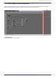
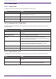
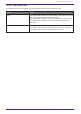
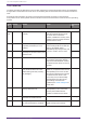
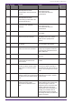
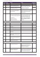
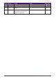
Table Of Contents
- ProVisionaire Design
- Contents
- 1. Introduction
- 2. Screen structure
- 3. The basics of using ProVisionaire Design
- 4. Menu bars and toolbar
- 5. Shortcut keys
- 6. List of alerts
- 7. "Project" sheet
- 8. "Tuning" sheet
- 9. Online and synchronization
- 10. Dialog boxes
- 10.1. Startup dialog box
- 10.2. "Go Online- From Devices" dialog box
- 10.3. "Protect File" dialog box
- 10.4. "Project Information" dialog box
- 10.5. "Print" dialog box
- 10.6. "File Storage" dialog box
- 10.7. "Network Setup" dialog box
- 10.8. "IP Settings" dialog box
- 10.9. "IP Address" dialog box
- 10.10. "Auto-Assign IP Addresses" dialog box
- 10.11. "Match Devices by IP Address" dialog box
- 10.12. "Device Information" dialog box
- 10.13. "Update Firmware" dialog box
- 10.14. "Initialize" dialog box
- 10.15. "Word Clock" dialog box
- 10.16. "Protect Devices" dialog box
- 10.17. "Clock" dialog box
- 10.18. "Daylight Saving Time" dialog box
- 10.19. "GPI Calibration" dialog box
- 10.20. "Get Log from Devices" dialog box
- 10.21. "RM Series Settings" > "Sign up" dialog box
- 10.22. "RM Series Settings" > "Login" dialog box
- 10.23. "RM Series Settings" > "Password Settings" dialog box
- 10.24. "RM Series Settings" > "Enable SCP remote control access" dialog box
- 10.25. "Linked Presets Manager" dialog box
- 10.26. "Store Linked Preset" dialog box
- 10.27. Port Label Dialog
- 11. Context menus
- 12. Common operations for device sheets
- 13. Audio Processors: DME7
- 13.1. Overview
- 13.2. "Project" sheet
- 13.3. Device sheet screen configuration
- 13.4. Basic use of ProVisonaire Designer
- 13.5. Tool buttons
- 13.6. "Components" area
- 13.7. Design sheet
- 13.8. Design sheet: Audio layer
- 13.9. Design sheet: Control layer
- 13.10. Components other than audio or control components
- 13.11. “Parameter Sets” area
- 13.12. “Properties” area
- 13.13. "Parameters" area
- 13.14. Context Menu
- 13.15. Dialog box
- 13.16. Message List
- 14. Audio Processor MRX7-D
- 14.1. Overview
- 14.2. Project Sheet
- 14.3. Device Sheet Screen Configuration
- 14.4. Basic Use
- 14.5. Tool Buttons
- 14.6. Components Area
- 14.7. Design Sheet
- 14.8. Non-Audio Components
- 14.9. Parameter Sets Area
- 14.10. Presets Area
- 14.11. Parameter Link Group Area
- 14.12. Gang Edit Group Area
- 14.13. Properties Area
- 14.14. Parameters Area
- 14.15. Context Menu
- 14.16. Dialog
- 14.17. Component Editor
- 14.18. Alert List
- 14.19. Flow of Paging Configuration
- 15. Audio Processors: MTX5-D/MTX3
- 15.1. Overview
- 15.2. "Project" sheet
- 15.3. Device sheet screen configuration
- 15.4. Tool buttons
- 15.5. "Presets" area
- 15.6. Context menus
- 15.7. Dialog box
- 15.8. Alert list
- 15.9. Component editors
- 15.9.1. "Analog In" component editor
- 15.9.2. “MY4-AEC” component editor
- 15.9.3. "Input CH" component editor
- 15.9.4. "Insert" component editor
- 15.9.5. "Zone" component editor
- 15.9.6. "Output CH" component editor
- 15.9.7. "Pilot Tone" component editor
- 15.9.8. "Analog Out" component editor
- 15.9.9. "Slot Out" component editor
- 15.9.10. "DCA Groups"/"Mute Groups" component editor
- 15.10. Workflow for paging settings
- 16. MTX I/O Expanders: EXi8 / Exo8
- 17. Power Amplifiers: PC-series
- 18. Power Amplifiers: XMV-series
- 19. I/O Interface: Rio3224-D2 / Rio1608-D2
- 20. I/O Interface: Tio1608-D / Tio1608-D2
- 21. I/O Interface: RSio64-D
- 22. Powered Speakers: VXL1-16P
- 23. Microphones: PGM1
- 24. Microphones: RM-CG
- 25. Microphones: RM-TT
- 26. External Device: Speakers
- 27. DCP
- 28. Wall-mount Controller: MCP1
- 29. YDIF
- 30. Settings for controlling devices across subnets
-

18.6. Alert list
The alerts generated by XMV-series units, and their significance and the appropriate actions, are listed below.
A single alert is shown when the event occurs. A continuing alert is shown when the event occurs and when it
ends.
Some alerts and information are shown in ProVisionaire Design but not shown on the unit itself.
If the problem is not solved, please contact a Yamaha service center listed at the end of the device’s operating
manual.
Numb
er
Severity Content Action Single/Contin
uing
Device abnormality
001~
008
Fault The device has not started up
correctly.
Turn the power off, wait at least five
seconds, and then turn the power
on. If this does not solve the
problem, initialize the memory. If the
problem is still not solved, contact a
Yamaha service center.
Continuing
10 Fault The internal backup battery is
completely exhausted, or is not
installed.
When you turn off the power, the
current settings will be lost and will
return to the default values.
Immediately stop using the unit, and
contact a Yamaha service center.
Continuing
11 Error The internal backup battery is
extremely low, and the memory may
have been lost.
Continuing
12 Warning The internal backup battery is low. The unit will operate correctly, but if
you continue using it the settings
may be lost and initialized. Contact
a Yamaha service center as soon as
possible.
Single
13 Fault An error occurred in the internal
clock, and it has been set to the
default value (year 2000, January
1st, midnight).
If this occurs each time you turn the
power on, it may be that the internal
backup battery has run low or that
the unit has malfunctioned. Contact
a Yamaha service center. If this
occurs only once, an abnormality
was detected in the value of the
clock setting and it has been
initialized; use "Clock" dialog box to
set the time.
Continuing
15 Fault The settings saved in internal
memory have been lost.
It is possible that the internal
backup battery is low, or that the
unit may have malfunctioned.
Contact a Yamaha service center.
Continuing
16 Fault It might be that the internal memory
of the unit has malfunctioned.
Contact a Yamaha service center. Continuing
21 Error The digital signal that is selected as
the word clock leader is unlocked.
Check whether the word clock
signal is being input correctly.
Continuing
18. Power Amplifiers: XMV-series
324 | ProVisionaire Design V1.2 User Guide