
User Manual

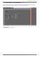
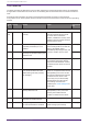
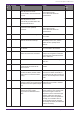
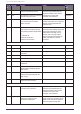
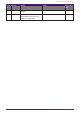
Table Of Contents
- ProVisionaire Design
- Contents
- 1. Introduction
- 2. Screen structure
- 3. The basics of using ProVisionaire Design
- 4. Menu bars and toolbar
- 5. Shortcut keys
- 6. List of alerts
- 7. "Project" sheet
- 8. "Tuning" sheet
- 9. Online and synchronization
- 10. Dialog boxes
- 10.1. Startup dialog box
- 10.2. "Go Online- From Devices" dialog box
- 10.3. "Protect File" dialog box
- 10.4. "Project Information" dialog box
- 10.5. "Print" dialog box
- 10.6. "File Storage" dialog box
- 10.7. "Network Setup" dialog box
- 10.8. "IP Settings" dialog box
- 10.9. "IP Address" dialog box
- 10.10. "Auto-Assign IP Addresses" dialog box
- 10.11. "Match Devices by IP Address" dialog box
- 10.12. "Device Information" dialog box
- 10.13. "Update Firmware" dialog box
- 10.14. "Initialize" dialog box
- 10.15. "Word Clock" dialog box
- 10.16. "Protect Devices" dialog box
- 10.17. "Clock" dialog box
- 10.18. "Daylight Saving Time" dialog box
- 10.19. "GPI Calibration" dialog box
- 10.20. "Get Log from Devices" dialog box
- 10.21. "RM Series Settings" > "Sign up" dialog box
- 10.22. "RM Series Settings" > "Login" dialog box
- 10.23. "RM Series Settings" > "Password Settings" dialog box
- 10.24. "RM Series Settings" > "Enable SCP remote control access" dialog box
- 10.25. "Linked Presets Manager" dialog box
- 10.26. "Store Linked Preset" dialog box
- 10.27. Port Label Dialog
- 11. Context menus
- 12. Common operations for device sheets
- 13. Audio Processors: DME7
- 13.1. Overview
- 13.2. "Project" sheet
- 13.3. Device sheet screen configuration
- 13.4. Basic use of ProVisonaire Designer
- 13.5. Tool buttons
- 13.6. "Components" area
- 13.7. Design sheet
- 13.8. Design sheet: Audio layer
- 13.9. Design sheet: Control layer
- 13.10. Components other than audio or control components
- 13.11. “Parameter Sets” area
- 13.12. “Properties” area
- 13.13. "Parameters" area
- 13.14. Context Menu
- 13.15. Dialog box
- 13.16. Message List
- 14. Audio Processor MRX7-D
- 14.1. Overview
- 14.2. Project Sheet
- 14.3. Device Sheet Screen Configuration
- 14.4. Basic Use
- 14.5. Tool Buttons
- 14.6. Components Area
- 14.7. Design Sheet
- 14.8. Non-Audio Components
- 14.9. Parameter Sets Area
- 14.10. Presets Area
- 14.11. Parameter Link Group Area
- 14.12. Gang Edit Group Area
- 14.13. Properties Area
- 14.14. Parameters Area
- 14.15. Context Menu
- 14.16. Dialog
- 14.17. Component Editor
- 14.18. Alert List
- 14.19. Flow of Paging Configuration
- 15. Audio Processors: MTX5-D/MTX3
- 15.1. Overview
- 15.2. "Project" sheet
- 15.3. Device sheet screen configuration
- 15.4. Tool buttons
- 15.5. "Presets" area
- 15.6. Context menus
- 15.7. Dialog box
- 15.8. Alert list
- 15.9. Component editors
- 15.9.1. "Analog In" component editor
- 15.9.2. “MY4-AEC” component editor
- 15.9.3. "Input CH" component editor
- 15.9.4. "Insert" component editor
- 15.9.5. "Zone" component editor
- 15.9.6. "Output CH" component editor
- 15.9.7. "Pilot Tone" component editor
- 15.9.8. "Analog Out" component editor
- 15.9.9. "Slot Out" component editor
- 15.9.10. "DCA Groups"/"Mute Groups" component editor
- 15.10. Workflow for paging settings
- 16. MTX I/O Expanders: EXi8 / Exo8
- 17. Power Amplifiers: PC-series
- 18. Power Amplifiers: XMV-series
- 19. I/O Interface: Rio3224-D2 / Rio1608-D2
- 20. I/O Interface: Tio1608-D / Tio1608-D2
- 21. I/O Interface: RSio64-D
- 22. Powered Speakers: VXL1-16P
- 23. Microphones: PGM1
- 24. Microphones: RM-CG
- 25. Microphones: RM-TT
- 26. External Device: Speakers
- 27. DCP
- 28. Wall-mount Controller: MCP1
- 29. YDIF
- 30. Settings for controlling devices across subnets
-

Numb
er
Severity Content Action Single/Contin
uing
22 Error The digital signal being input to the
[YDIF IN] connector is not
synchronized to the word clock of
this unit.
Check whether the cable is
connected correctly.
Use a cable that meets the
specifications.
Single
23 Error The digital signal being input to the
[YDIF IN] connector is not
continuously synchronized to the
word clock of this unit.
Continuing
30 Error There is a problem with the
connection of the [YDIF IN]
connector.
Check whether the cable is
connected correctly.
Use a cable that meets the
specifications.
Continuing
40 Error The IP address is conflicting. Set the IP address so that it does
not conflict.
Continuing
41 Warning The IP address was not established
within 60 seconds of start-up.
If the device’s DIP switch 6 (IP
SETTING) is set to "PC," use the
DHCP server to specify the IP
address.
Continuing
43 Error Too many devices are connected to
the network.
Reduce the number of devices that
are connected to the network.
Single
46 Error The Dante transmission flow
number limit has been exceeded.
Reduce the flow number, for
example by using Dante Controller
to change part of the transmission
flow to multicast.
Single
50 Error The UNIT ID is set to "00." Set the UNIT ID to something other
than "00."
Continuing
51 Error Another device with the same UNIT
ID was found connected to the
same network.
Set the UNIT ID so that it does not
conflict.
Continuing
72 Error Because Device Lock has been
specified for Dante, the DIP switch
setting does not match the Dante
setting.
If Device Lock is specified, either
cancel it from Dante Controller, or
reconsider the DIP switch setting so
that it is set correctly for the current
state.
Continuing
100 Fault The power supply was shut down
because a direct current component
was detected at the speaker output
jack.
It is likely that the unit has
malfunctioned; contact a Yamaha
service center.
Continuing
101 Fault The power supply was shut down
because the power supply
temperature exceeded the rated
value.
Turn off the power, wait for the
power supply to cool, and then turn
the power on again. Lower the
output level, since continuous high
wattage output will cause high
temperatures. If the temperature is
still high, check whether dust or
foreign matter might be clogging
the cooling fan intake, and clean the
intake if necessary.
Continuing
18. Power Amplifiers: XMV-series
ProVisionaire Design V1.2 User Guide | 325