
User Manual
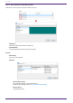
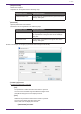

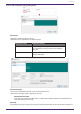
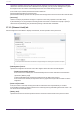
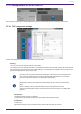
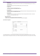
Table Of Contents
- ProVisionaire Design
- Contents
- 1. Introduction
- 2. Screen structure
- 3. The basics of using ProVisionaire Design
- 4. Menu bars and toolbar
- 5. Shortcut keys
- 6. List of alerts
- 7. "Project" sheet
- 8. "Tuning" sheet
- 9. Online and synchronization
- 10. Dialog boxes
- 10.1. Startup dialog box
- 10.2. "Go Online- From Devices" dialog box
- 10.3. "Protect File" dialog box
- 10.4. "Project Information" dialog box
- 10.5. "Print" dialog box
- 10.6. "File Storage" dialog box
- 10.7. "Network Setup" dialog box
- 10.8. "IP Settings" dialog box
- 10.9. "IP Address" dialog box
- 10.10. "Auto-Assign IP Addresses" dialog box
- 10.11. "Match Devices by IP Address" dialog box
- 10.12. "Device Information" dialog box
- 10.13. "Update Firmware" dialog box
- 10.14. "Initialize" dialog box
- 10.15. "Word Clock" dialog box
- 10.16. "Protect Devices" dialog box
- 10.17. "Clock" dialog box
- 10.18. "Daylight Saving Time" dialog box
- 10.19. "GPI Calibration" dialog box
- 10.20. "Get Log from Devices" dialog box
- 10.21. "RM Series Settings" > "Sign up" dialog box
- 10.22. "RM Series Settings" > "Login" dialog box
- 10.23. "RM Series Settings" > "Password Settings" dialog box
- 10.24. "RM Series Settings" > "Enable SCP remote control access" dialog box
- 10.25. "Linked Presets Manager" dialog box
- 10.26. "Store Linked Preset" dialog box
- 10.27. Port Label Dialog
- 11. Context menus
- 12. Common operations for device sheets
- 13. Audio Processors: DME7
- 13.1. Overview
- 13.2. "Project" sheet
- 13.3. Device sheet screen configuration
- 13.4. Basic use of ProVisonaire Designer
- 13.5. Tool buttons
- 13.6. "Components" area
- 13.7. Design sheet
- 13.8. Design sheet: Audio layer
- 13.9. Design sheet: Control layer
- 13.10. Components other than audio or control components
- 13.11. “Parameter Sets” area
- 13.12. “Properties” area
- 13.13. "Parameters" area
- 13.14. Context Menu
- 13.15. Dialog box
- 13.16. Message List
- 14. Audio Processor MRX7-D
- 14.1. Overview
- 14.2. Project Sheet
- 14.3. Device Sheet Screen Configuration
- 14.4. Basic Use
- 14.5. Tool Buttons
- 14.6. Components Area
- 14.7. Design Sheet
- 14.8. Non-Audio Components
- 14.9. Parameter Sets Area
- 14.10. Presets Area
- 14.11. Parameter Link Group Area
- 14.12. Gang Edit Group Area
- 14.13. Properties Area
- 14.14. Parameters Area
- 14.15. Context Menu
- 14.16. Dialog
- 14.17. Component Editor
- 14.18. Alert List
- 14.19. Flow of Paging Configuration
- 15. Audio Processors: MTX5-D/MTX3
- 15.1. Overview
- 15.2. "Project" sheet
- 15.3. Device sheet screen configuration
- 15.4. Tool buttons
- 15.5. "Presets" area
- 15.6. Context menus
- 15.7. Dialog box
- 15.8. Alert list
- 15.9. Component editors
- 15.9.1. "Analog In" component editor
- 15.9.2. “MY4-AEC” component editor
- 15.9.3. "Input CH" component editor
- 15.9.4. "Insert" component editor
- 15.9.5. "Zone" component editor
- 15.9.6. "Output CH" component editor
- 15.9.7. "Pilot Tone" component editor
- 15.9.8. "Analog Out" component editor
- 15.9.9. "Slot Out" component editor
- 15.9.10. "DCA Groups"/"Mute Groups" component editor
- 15.10. Workflow for paging settings
- 16. MTX I/O Expanders: EXi8 / Exo8
- 17. Power Amplifiers: PC-series
- 18. Power Amplifiers: XMV-series
- 19. I/O Interface: Rio3224-D2 / Rio1608-D2
- 20. I/O Interface: Tio1608-D / Tio1608-D2
- 21. I/O Interface: RSio64-D
- 22. Powered Speakers: VXL1-16P
- 23. Microphones: PGM1
- 24. Microphones: RM-CG
- 25. Microphones: RM-TT
- 26. External Device: Speakers
- 27. DCP
- 28. Wall-mount Controller: MCP1
- 29. YDIF
- 30. Settings for controlling devices across subnets
-

example by specifying the center LED as the volume setting for normal use and setting the maximum
value to the maximum volume that is allowable for the system, you can prevent damage to the system
that might occur if the volume of the background music were raised during a noisy time.
If the check box is selected, the Nominal function will be on.
[Nominal Value] specifies the nominal value.
[Nominal LED Position] specifies the LED position that will light when the level reaches the nominal value.
•
[Sensitivity]
Sets the sensitivity of parameter changes in response to the rotary operation of the DCP knob.
If [Acceleration] is on, the parameter will change faster if the knob is rotated more rapidly. If [Fast] is
selected as the [Sensitivity], the [Acceleration] setting is dimmed and unavailable.
27.3.3. [Dimmer & Lock] tab
Sets the brightness of the MCP1’s display and switches, and the operation of the panel lock.
•
[LED Brightness] list box
Specifies the brightness of the DCP unit’s LEDs. Higher values will make the LEDs brighter.
◦ [Enable Inactive Mode] check box
If the check box is selected, the unit automatically enters inactive mode after a time duration
specified in [Waiting Time].
[Inactive LED Brightness] specifies the brightness of the LEDs when inactive.
If the check box is cleared, the drop-down menu is grayed-out and you will be unable to set the
brightness.
•
[Panel Lock] check box
If this check box is selected, the DCP panel will be locked when the snapshot library is recalled.
If the [Enable Temporary Unlocking] check box is selected, pressing and holding down DCP switch 1 for
two seconds will unlock the panel.
•
[Waiting Time]
Specifies the time from the last operation until the unit enters inactive mode or the panel is locked.
27. DCP
376 | ProVisionaire Design V1.2 User Guide