
User Manual
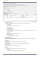

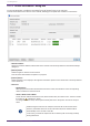
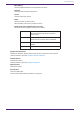
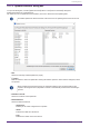
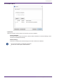
Table Of Contents
- ProVisionaire Design
- Contents
- 1. Introduction
- 2. Screen structure
- 3. The basics of using ProVisionaire Design
- 4. Menu bars and toolbar
- 5. Shortcut keys
- 6. List of alerts
- 7. "Project" sheet
- 8. "Tuning" sheet
- 9. Online and synchronization
- 10. Dialog boxes
- 10.1. Startup dialog box
- 10.2. "Go Online- From Devices" dialog box
- 10.3. "Protect File" dialog box
- 10.4. "Project Information" dialog box
- 10.5. "Print" dialog box
- 10.6. "File Storage" dialog box
- 10.7. "Network Setup" dialog box
- 10.8. "IP Settings" dialog box
- 10.9. "IP Address" dialog box
- 10.10. "Auto-Assign IP Addresses" dialog box
- 10.11. "Match Devices by IP Address" dialog box
- 10.12. "Device Information" dialog box
- 10.13. "Update Firmware" dialog box
- 10.14. "Initialize" dialog box
- 10.15. "Word Clock" dialog box
- 10.16. "Protect Devices" dialog box
- 10.17. "Clock" dialog box
- 10.18. "Daylight Saving Time" dialog box
- 10.19. "GPI Calibration" dialog box
- 10.20. "Get Log from Devices" dialog box
- 10.21. "RM Series Settings" > "Sign up" dialog box
- 10.22. "RM Series Settings" > "Login" dialog box
- 10.23. "RM Series Settings" > "Password Settings" dialog box
- 10.24. "RM Series Settings" > "Enable SCP remote control access" dialog box
- 10.25. "Linked Presets Manager" dialog box
- 10.26. "Store Linked Preset" dialog box
- 10.27. Port Label Dialog
- 11. Context menus
- 12. Common operations for device sheets
- 13. Audio Processors: DME7
- 13.1. Overview
- 13.2. "Project" sheet
- 13.3. Device sheet screen configuration
- 13.4. Basic use of ProVisonaire Designer
- 13.5. Tool buttons
- 13.6. "Components" area
- 13.7. Design sheet
- 13.8. Design sheet: Audio layer
- 13.9. Design sheet: Control layer
- 13.10. Components other than audio or control components
- 13.11. “Parameter Sets” area
- 13.12. “Properties” area
- 13.13. "Parameters" area
- 13.14. Context Menu
- 13.15. Dialog box
- 13.16. Message List
- 14. Audio Processor MRX7-D
- 14.1. Overview
- 14.2. Project Sheet
- 14.3. Device Sheet Screen Configuration
- 14.4. Basic Use
- 14.5. Tool Buttons
- 14.6. Components Area
- 14.7. Design Sheet
- 14.8. Non-Audio Components
- 14.9. Parameter Sets Area
- 14.10. Presets Area
- 14.11. Parameter Link Group Area
- 14.12. Gang Edit Group Area
- 14.13. Properties Area
- 14.14. Parameters Area
- 14.15. Context Menu
- 14.16. Dialog
- 14.17. Component Editor
- 14.18. Alert List
- 14.19. Flow of Paging Configuration
- 15. Audio Processors: MTX5-D/MTX3
- 15.1. Overview
- 15.2. "Project" sheet
- 15.3. Device sheet screen configuration
- 15.4. Tool buttons
- 15.5. "Presets" area
- 15.6. Context menus
- 15.7. Dialog box
- 15.8. Alert list
- 15.9. Component editors
- 15.9.1. "Analog In" component editor
- 15.9.2. “MY4-AEC” component editor
- 15.9.3. "Input CH" component editor
- 15.9.4. "Insert" component editor
- 15.9.5. "Zone" component editor
- 15.9.6. "Output CH" component editor
- 15.9.7. "Pilot Tone" component editor
- 15.9.8. "Analog Out" component editor
- 15.9.9. "Slot Out" component editor
- 15.9.10. "DCA Groups"/"Mute Groups" component editor
- 15.10. Workflow for paging settings
- 16. MTX I/O Expanders: EXi8 / Exo8
- 17. Power Amplifiers: PC-series
- 18. Power Amplifiers: XMV-series
- 19. I/O Interface: Rio3224-D2 / Rio1608-D2
- 20. I/O Interface: Tio1608-D / Tio1608-D2
- 21. I/O Interface: RSio64-D
- 22. Powered Speakers: VXL1-16P
- 23. Microphones: PGM1
- 24. Microphones: RM-CG
- 25. Microphones: RM-TT
- 26. External Device: Speakers
- 27. DCP
- 28. Wall-mount Controller: MCP1
- 29. YDIF
- 30. Settings for controlling devices across subnets
-

10.12. "Device Information" dialog box
To open this dialog box, click [Device Information] from the [System] menu on the menu bar.
This lists information for the devices on the network, allowing you to update their firmware or restart them.
•
Network Interface
Shows the name/IP address/subnet mask of the network card currently selected in the "Network Setup"
dialog box.
•
[Refresh] button
Searches again for devices on the network.
This cannot be clicked while an update is in progress.
•
[Detail>>] button
Switch this button on to display to the right the information specific to the device that is currently selected
on the device list.
• Device list
◦ Identify button
When you press this button located at the left of the Unit ID, the indicators of the corresponding
device will flash for several seconds.
◦ Unit ID / Model / Device Name
These columns indicate the device Unit ID, device model name, and device name. If there is a UNIT
ID conflict, an indication is shown.
To change the device name, use the [Device Name] field in the “Properties” area of the “Project”
sheet.
If different types of devices are used, the same Unit ID can be used for them.
However, if the MTX series unit is set to Unit ID mode, the IP address will be
automatically set to 192.168.0.<Unit ID>.
In this case, you must set unique Unit IDs so that they will not overlap (conflict)
among all devices.
10. Dialog boxes
82 | ProVisionaire Design V1.2 User Guide