
User Manual
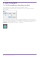
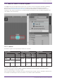

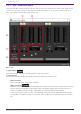
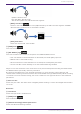
Table Of Contents
- ProVisionaire Design
- Contents
- 1. Introduction
- 2. Audio Components
- 2.1. The Difference Between Mono, Stereo, and Multi
- 2.2. How to Control Control Signals
- 2.3. Acoustic Echo Canceller (AEC)
- 2.4. Ambient Noise Compensator (ANC)
- 2.5. Audio Detector
- 2.6. Auto Gain Control (AGC)
- 2.7. Combiner: Room Combiner, Room Combiner plus Automixer
- 2.8. DCA
- 2.9. Delay
- 2.10. Dynamics: Compressor
- 2.11. Dynamics: Comp260
- 2.12. Dynamics: De-Esser
- 2.13. Dynamics: Ducker
- 2.14. Dynamics: Gate
- 2.15. Dynamics: Limiter
- 2.16. Dynamics: Paging Ducker
- 2.17. Dynamics: Program Ducker
- 2.18. Effect: Ping Pong Delay
- 2.19. Effect: REV-X
- 2.20. EQ: GEQ
- 2.21. EQ: PEQ
- 2.22. Fader
- 2.23. Feedback Suppressor: Notch FBS
- 2.24. Feedback Suppressor: Pitch Shift FBS
- 2.25. Filter: BPF
- 2.26. Filter: HPF
- 2.27. Filter: LPF
- 2.28. Input/Output: Dante In
- 2.29. Input/Output: USB In
- 2.30. Input/Output: Dante Out
- 2.31. Input/Output: USB Out
- 2.32. Input/Output: SD Card
- 2.33. Meter
- 2.34. Mixer: Delay Matrix, Matrix Mixer
- 2.35. Mixer: Dugan Automixer
- 2.36. Oscillator
- 2.37. Polarity
- 2.38. Probe
- 2.39. Router
- 2.40. Source Selector
- 2.41. Speaker Processor: Standard SPP
- 2.42. Speaker Processor: C-Series SPP (FIR)
- 3. Control Components
- 3.1. Control Methods for Control Components
- 3.2. Input (Normalized Value): Button
- 3.3. Input (Value): Button
- 3.4. Input (Normalized Value): Radio Button
- 3.5. Input (Value): Radio Button
- 3.6. Input (Normalized Value): Fader
- 3.7. Input (Value): Fader
- 3.8. Processing (Normalized Value): Logic
- 3.9. Processing (Normalized Value): NOT
- 3.10. Processing (Normalized Value): Flip-Flop
- 3.11. Processing (Normalized Value): Invert
- 3.12. Processing (Normalized Value): Compare
- 3.13. Processing (Normalized Value): Difference
- 3.14. Processing (Normalized Value): Max/Min
- 3.15. Processing (Value): Negate
- 3.16. Processing (Value): Compare
- 3.17. Processing (Value): Multi Compare
- 3.18. Processing (Value): Difference
- 3.19. Processing (Value): Max/Min
- 3.20. Processing: Delay
- 3.21. Processing: External Events
- 3.22. Processing: Suspend
- 3.23. Processing: Router
- 3.24. Controller: GPI In
- 3.25. Controller: GPI Out
- 3.26. Controller: Scheduler
- 3.27. Parameter Set
- 3.28. Snapshot

・Speaker volume is loud.
・Mic gain (MIC1, MIC2) is high.
・The mic and speaker are positioned close together.
•
[ERLE] level meter
Shows in real time the amount of echo (dB) removed by the AEC. The more negative the ERLE
value becomes, the more echo is removed by the AEC.
•
[OUT] level meter
Shows the output level from the AEC.
③ [GAIN] knob
This sets the mic gain.
④ [AEC EFFECT] type
This sets the AEC effect. There are 4 options: Soft/Medium/Hard/Custom.
• Soft: The amount of echo elimination is decreased, but sound quality improves.
• Medium: This is the initial setting.
• Hard: The amount of echo elimination is increased, but sound quality decreases.
• Custom: The AEC can be manually set on the Advanced Settings window.
Adjust to suit the conditions in the conference room (close location) while checking the audio. Please
use Medium unless specifically necessary otherwise.
By switching the AEC Effect type, multiple parameters for echo canceling, noise reduction, and
reverberation canceling can be switched to the recommended settings simultaneously. When switching
to Custom from a non-Custom setting, the current values for that type will be set in the Advanced
parameters.
⑤ Port text box
Shows the port name. The name can be changed by double clicking. It cannot be changed when AUTO is
set to On.
Reference
⑥ Level meter
Shows the input level from Reference.
⑦ [GAIN] knob
Sets the Reference gain.
⑧ [Advanced Settings] window open button
Shows the Advanced Settings window.
2. Audio Components
ProVisionaire Design Component Guide | 9