
User Manual
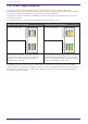
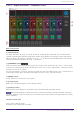
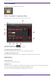
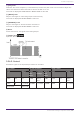
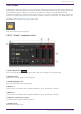
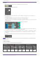
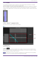
Table Of Contents
- ProVisionaire Design
- Contents
- 1. Introduction
- 2. Audio Components
- 2.1. The Difference Between Mono, Stereo, and Multi
- 2.2. How to Control Control Signals
- 2.3. Acoustic Echo Canceller (AEC)
- 2.4. Ambient Noise Compensator (ANC)
- 2.5. Audio Detector
- 2.6. Auto Gain Control (AGC)
- 2.7. Combiner: Room Combiner, Room Combiner plus Automixer
- 2.8. DCA
- 2.9. Delay
- 2.10. Dynamics: Compressor
- 2.11. Dynamics: Comp260
- 2.12. Dynamics: De-Esser
- 2.13. Dynamics: Ducker
- 2.14. Dynamics: Gate
- 2.15. Dynamics: Limiter
- 2.16. Dynamics: Paging Ducker
- 2.17. Dynamics: Program Ducker
- 2.18. Effect: Ping Pong Delay
- 2.19. Effect: REV-X
- 2.20. EQ: GEQ
- 2.21. EQ: PEQ
- 2.22. Fader
- 2.23. Feedback Suppressor: Notch FBS
- 2.24. Feedback Suppressor: Pitch Shift FBS
- 2.25. Filter: BPF
- 2.26. Filter: HPF
- 2.27. Filter: LPF
- 2.28. Input/Output: Dante In
- 2.29. Input/Output: USB In
- 2.30. Input/Output: Dante Out
- 2.31. Input/Output: USB Out
- 2.32. Input/Output: SD Card
- 2.33. Meter
- 2.34. Mixer: Delay Matrix, Matrix Mixer
- 2.35. Mixer: Dugan Automixer
- 2.36. Oscillator
- 2.37. Polarity
- 2.38. Probe
- 2.39. Router
- 2.40. Source Selector
- 2.41. Speaker Processor: Standard SPP
- 2.42. Speaker Processor: C-Series SPP (FIR)
- 3. Control Components
- 3.1. Control Methods for Control Components
- 3.2. Input (Normalized Value): Button
- 3.3. Input (Value): Button
- 3.4. Input (Normalized Value): Radio Button
- 3.5. Input (Value): Radio Button
- 3.6. Input (Normalized Value): Fader
- 3.7. Input (Value): Fader
- 3.8. Processing (Normalized Value): Logic
- 3.9. Processing (Normalized Value): NOT
- 3.10. Processing (Normalized Value): Flip-Flop
- 3.11. Processing (Normalized Value): Invert
- 3.12. Processing (Normalized Value): Compare
- 3.13. Processing (Normalized Value): Difference
- 3.14. Processing (Normalized Value): Max/Min
- 3.15. Processing (Value): Negate
- 3.16. Processing (Value): Compare
- 3.17. Processing (Value): Multi Compare
- 3.18. Processing (Value): Difference
- 3.19. Processing (Value): Max/Min
- 3.20. Processing: Delay
- 3.21. Processing: External Events
- 3.22. Processing: Suspend
- 3.23. Processing: Router
- 3.24. Controller: GPI In
- 3.25. Controller: GPI Out
- 3.26. Controller: Scheduler
- 3.27. Parameter Set
- 3.28. Snapshot

① [level] indicator
This lights green when the audio reaches the appropriate level for automixing.
・If the [level] indicator goes dark, raise the input gain.
・If the [level] indicator turns red, lower the input gain.
② Meter
The meter provides three display modes: gain (green: automix gain) /input (yellow: input level) /output
(blue: output level). The display mode switches each time you press the [meters] button in the main
control field.
③ [weight] slider
Adjusts the relative sensitivity between input channels. Set the meter display to “gain,” and adjust the
weight setting so that the meters are at approximately the same level when there is no input. For
example if noise is heard near a certain mic (e.g., air conditioner wind noise), lowering the weight value
of that channel will reduce the noise.
The automixer calculates the proportion of a specific channel’s input level relative to the mix of all
inputs in the group. The following examples describe how weight control works.
● If the weight setting value is raised on one channel
• The automix gain value of that channel increases, and the value of other channels decreases.
• Channels with a high weight setting will more easily obtain automix gain in comparison to other
channels.
● If the weight setting value is lowered on one channel
• The automix gain value of that channel decreases, and the value of other channels increases.
• If people speak simultaneously into multiple mics, it will be more difficult to differentiate them
from the other mics.
④ [group] button
Selects the group to which each channel belongs. Click the button to switch the group.
⑤ [override] button
When the main control field’s [OVERRIDE] button is on, the setting of this button determines whether
the corresponding channel switches to “man” mode or “mute” mode.
• If you turn on the [OVERRIDE] button of the main control field when the [override] button of
the channel control field is on, the channel mode changes to “man.”
2. Audio Components
102 | ProVisionaire Design Component Guide