
User Manual
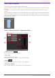
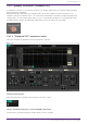
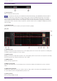
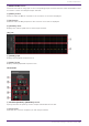
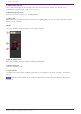
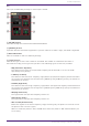
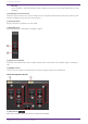
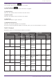
Table Of Contents
- ProVisionaire Design
- Contents
- 1. Introduction
- 2. Audio Components
- 2.1. The Difference Between Mono, Stereo, and Multi
- 2.2. How to Control Control Signals
- 2.3. Acoustic Echo Canceller (AEC)
- 2.4. Ambient Noise Compensator (ANC)
- 2.5. Audio Detector
- 2.6. Auto Gain Control (AGC)
- 2.7. Combiner: Room Combiner, Room Combiner plus Automixer
- 2.8. DCA
- 2.9. Delay
- 2.10. Dynamics: Compressor
- 2.11. Dynamics: Comp260
- 2.12. Dynamics: De-Esser
- 2.13. Dynamics: Ducker
- 2.14. Dynamics: Gate
- 2.15. Dynamics: Limiter
- 2.16. Dynamics: Paging Ducker
- 2.17. Dynamics: Program Ducker
- 2.18. Effect: Ping Pong Delay
- 2.19. Effect: REV-X
- 2.20. EQ: GEQ
- 2.21. EQ: PEQ
- 2.22. Fader
- 2.23. Feedback Suppressor: Notch FBS
- 2.24. Feedback Suppressor: Pitch Shift FBS
- 2.25. Filter: BPF
- 2.26. Filter: HPF
- 2.27. Filter: LPF
- 2.28. Input/Output: Dante In
- 2.29. Input/Output: USB In
- 2.30. Input/Output: Dante Out
- 2.31. Input/Output: USB Out
- 2.32. Input/Output: SD Card
- 2.33. Meter
- 2.34. Mixer: Delay Matrix, Matrix Mixer
- 2.35. Mixer: Dugan Automixer
- 2.36. Oscillator
- 2.37. Polarity
- 2.38. Probe
- 2.39. Router
- 2.40. Source Selector
- 2.41. Speaker Processor: Standard SPP
- 2.42. Speaker Processor: C-Series SPP (FIR)
- 3. Control Components
- 3.1. Control Methods for Control Components
- 3.2. Input (Normalized Value): Button
- 3.3. Input (Value): Button
- 3.4. Input (Normalized Value): Radio Button
- 3.5. Input (Value): Radio Button
- 3.6. Input (Normalized Value): Fader
- 3.7. Input (Value): Fader
- 3.8. Processing (Normalized Value): Logic
- 3.9. Processing (Normalized Value): NOT
- 3.10. Processing (Normalized Value): Flip-Flop
- 3.11. Processing (Normalized Value): Invert
- 3.12. Processing (Normalized Value): Compare
- 3.13. Processing (Normalized Value): Difference
- 3.14. Processing (Normalized Value): Max/Min
- 3.15. Processing (Value): Negate
- 3.16. Processing (Value): Compare
- 3.17. Processing (Value): Multi Compare
- 3.18. Processing (Value): Difference
- 3.19. Processing (Value): Max/Min
- 3.20. Processing: Delay
- 3.21. Processing: External Events
- 3.22. Processing: Suspend
- 3.23. Processing: Router
- 3.24. Controller: GPI In
- 3.25. Controller: GPI Out
- 3.26. Controller: Scheduler
- 3.27. Parameter Set
- 3.28. Snapshot

Pre-installed LIBRARY
① [LIST] button
Selects and shows library items.
In the libraries that are pre-installed in ProVisionaire Design, the LIMITER’s Threshold value is
set to the value that is appropriate when using a power amp with 26 dB voltage gain. As necessary,
make appropriate adjustments to the DME7’s LIMITER settings and output level, and to the power
amp’s voltage gain and attenuator. For example if using a power amp whose voltage gain is 30 dB, you
should either lower the power amp’s attenuator value by 4 dB or lower the DME7’s LIMITER Threshold
value by 4 dB.
② [STORE] button
Saves the current state as a library item (file extension [.spld]).
[SP] tab
① [PHASE] graph
Displays a crossover phase response curve. This display takes into account the response of the PEQ and
the Delay. Output channels are color-coded.
② [LEVEL] graph
Displays a crossover amplitude response curve. This display takes into account the response of the PEQ
and the Output Level. Output channels are color-coded.
③ [INPUT] meter
Shows the input signal level.
④ INPUT [Level] knob
Specifies the input level. You can double-click the numeric display area and directly enter a numeric
value.
⑤ [Band Select] buttons
If a button is selected, the current value is shown in "EQ," below. For bands whose [BYPASS] button is
on, the indicator below that [Band Select] button is lit.
⑥ [FLAT] button
Sets the "EQ" [GAIN] to 0 dB.
2. Audio Components
114 | ProVisionaire Design Component Guide