
User Manual
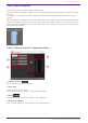
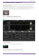
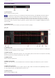
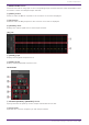
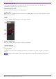
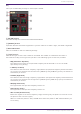
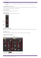
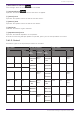
Table Of Contents
- ProVisionaire Design
- Contents
- 1. Introduction
- 2. Audio Components
- 2.1. The Difference Between Mono, Stereo, and Multi
- 2.2. How to Control Control Signals
- 2.3. Acoustic Echo Canceller (AEC)
- 2.4. Ambient Noise Compensator (ANC)
- 2.5. Audio Detector
- 2.6. Auto Gain Control (AGC)
- 2.7. Combiner: Room Combiner, Room Combiner plus Automixer
- 2.8. DCA
- 2.9. Delay
- 2.10. Dynamics: Compressor
- 2.11. Dynamics: Comp260
- 2.12. Dynamics: De-Esser
- 2.13. Dynamics: Ducker
- 2.14. Dynamics: Gate
- 2.15. Dynamics: Limiter
- 2.16. Dynamics: Paging Ducker
- 2.17. Dynamics: Program Ducker
- 2.18. Effect: Ping Pong Delay
- 2.19. Effect: REV-X
- 2.20. EQ: GEQ
- 2.21. EQ: PEQ
- 2.22. Fader
- 2.23. Feedback Suppressor: Notch FBS
- 2.24. Feedback Suppressor: Pitch Shift FBS
- 2.25. Filter: BPF
- 2.26. Filter: HPF
- 2.27. Filter: LPF
- 2.28. Input/Output: Dante In
- 2.29. Input/Output: USB In
- 2.30. Input/Output: Dante Out
- 2.31. Input/Output: USB Out
- 2.32. Input/Output: SD Card
- 2.33. Meter
- 2.34. Mixer: Delay Matrix, Matrix Mixer
- 2.35. Mixer: Dugan Automixer
- 2.36. Oscillator
- 2.37. Polarity
- 2.38. Probe
- 2.39. Router
- 2.40. Source Selector
- 2.41. Speaker Processor: Standard SPP
- 2.42. Speaker Processor: C-Series SPP (FIR)
- 3. Control Components
- 3.1. Control Methods for Control Components
- 3.2. Input (Normalized Value): Button
- 3.3. Input (Value): Button
- 3.4. Input (Normalized Value): Radio Button
- 3.5. Input (Value): Radio Button
- 3.6. Input (Normalized Value): Fader
- 3.7. Input (Value): Fader
- 3.8. Processing (Normalized Value): Logic
- 3.9. Processing (Normalized Value): NOT
- 3.10. Processing (Normalized Value): Flip-Flop
- 3.11. Processing (Normalized Value): Invert
- 3.12. Processing (Normalized Value): Compare
- 3.13. Processing (Normalized Value): Difference
- 3.14. Processing (Normalized Value): Max/Min
- 3.15. Processing (Value): Negate
- 3.16. Processing (Value): Compare
- 3.17. Processing (Value): Multi Compare
- 3.18. Processing (Value): Difference
- 3.19. Processing (Value): Max/Min
- 3.20. Processing: Delay
- 3.21. Processing: External Events
- 3.22. Processing: Suspend
- 3.23. Processing: Router
- 3.24. Controller: GPI In
- 3.25. Controller: GPI Out
- 3.26. Controller: Scheduler
- 3.27. Parameter Set
- 3.28. Snapshot

EQ
Here you can make PEQ settings for each output channel.
① EQ [ON] button
Switches the EQ function between enabled and disabled.
② [BYPASS] button
Specifies whether each band is bypassed. If you click a button to make it light, that band is bypassed.
③ Band slide banner
Selects the band for which to make EQ settings.
④ [Type] list box
Selects the type of filter that is used for each band. The number of knobs below increases or
decreases according to the type that you select. The following types of filter are provided.
•
PEQ (Parametric Equalizer)
The volume in the region of the specified frequency will be boosted or cut for the width
specified by the Q setting.
•
L.SHELF (Low Shelf)
The volume of the entire low-frequency region below the specified frequency will be boosted or
cut. Use this for purposes such as bass boost. [6dB/Oct] and [12dB/Oct] specify the amount of
attenuation per octave.
•
H.SHELF (High Shelf)
The volume of the entire high-frequency region above the specified frequency will be boosted or
cut. Use this for purposes such as high boost. [6dB/Oct] and [12dB/ Oct] specify the amount of
attenuation per octave.
•
HPF(High Pass Filter)
The region below the specified frequency will be cut.
•
LPF(Low Pass Filter)
The region above the specified frequency will be cut.
•
APF 1st/2nd (All Pass Filter)
Passes the signals of the entire frequency range, affecting only the phase. It is used to correct
the phase of the crossover region.
APF 1st rotates the phase 0˚–180˚, and APF 2nd rotates the phase 0˚–360˚. APF 2nd allows you
to set the Q.
2. Audio Components
ProVisionaire Design Component Guide | 117