
User Manual
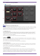
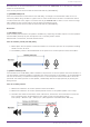
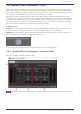
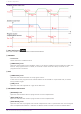
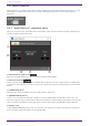
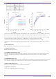
Table Of Contents
- ProVisionaire Design
- Contents
- 1. Introduction
- 2. Audio Components
- 2.1. The Difference Between Mono, Stereo, and Multi
- 2.2. How to Control Control Signals
- 2.3. Acoustic Echo Canceller (AEC)
- 2.4. Ambient Noise Compensator (ANC)
- 2.5. Audio Detector
- 2.6. Auto Gain Control (AGC)
- 2.7. Combiner: Room Combiner, Room Combiner plus Automixer
- 2.8. DCA
- 2.9. Delay
- 2.10. Dynamics: Compressor
- 2.11. Dynamics: Comp260
- 2.12. Dynamics: De-Esser
- 2.13. Dynamics: Ducker
- 2.14. Dynamics: Gate
- 2.15. Dynamics: Limiter
- 2.16. Dynamics: Paging Ducker
- 2.17. Dynamics: Program Ducker
- 2.18. Effect: Ping Pong Delay
- 2.19. Effect: REV-X
- 2.20. EQ: GEQ
- 2.21. EQ: PEQ
- 2.22. Fader
- 2.23. Feedback Suppressor: Notch FBS
- 2.24. Feedback Suppressor: Pitch Shift FBS
- 2.25. Filter: BPF
- 2.26. Filter: HPF
- 2.27. Filter: LPF
- 2.28. Input/Output: Dante In
- 2.29. Input/Output: USB In
- 2.30. Input/Output: Dante Out
- 2.31. Input/Output: USB Out
- 2.32. Input/Output: SD Card
- 2.33. Meter
- 2.34. Mixer: Delay Matrix, Matrix Mixer
- 2.35. Mixer: Dugan Automixer
- 2.36. Oscillator
- 2.37. Polarity
- 2.38. Probe
- 2.39. Router
- 2.40. Source Selector
- 2.41. Speaker Processor: Standard SPP
- 2.42. Speaker Processor: C-Series SPP (FIR)
- 3. Control Components
- 3.1. Control Methods for Control Components
- 3.2. Input (Normalized Value): Button
- 3.3. Input (Value): Button
- 3.4. Input (Normalized Value): Radio Button
- 3.5. Input (Value): Radio Button
- 3.6. Input (Normalized Value): Fader
- 3.7. Input (Value): Fader
- 3.8. Processing (Normalized Value): Logic
- 3.9. Processing (Normalized Value): NOT
- 3.10. Processing (Normalized Value): Flip-Flop
- 3.11. Processing (Normalized Value): Invert
- 3.12. Processing (Normalized Value): Compare
- 3.13. Processing (Normalized Value): Difference
- 3.14. Processing (Normalized Value): Max/Min
- 3.15. Processing (Value): Negate
- 3.16. Processing (Value): Compare
- 3.17. Processing (Value): Multi Compare
- 3.18. Processing (Value): Difference
- 3.19. Processing (Value): Max/Min
- 3.20. Processing: Delay
- 3.21. Processing: External Events
- 3.22. Processing: Suspend
- 3.23. Processing: Router
- 3.24. Controller: GPI In
- 3.25. Controller: GPI Out
- 3.26. Controller: Scheduler
- 3.27. Parameter Set
- 3.28. Snapshot

Reverberation is not removed when set to 0. Best used with "DEREVERB" set to Off (0) for rooms with
almost no reverberation.
This can only be set when Custom has been selected for [AEC EFFECT].
⑤ [REVERB TIME] knob
Sets the reverberation time inside a room. Normally, no change from the Default value of 0.6 s is
necessary. When using the AEC in a glass room or other location that has more reverberation than a
normal conference room, adjust to increase the target REVERB TIME to 0.6–1.0 s. For events in large
halls, please set the reverb time to suit the hall’s reverberation time.
This can only be set when Custom has been selected for [AEC EFFECT].
Reference
⑥ [FE DELAY] knob
Sets the delay time between the speakers and MIC1 by comparing the audio output from the speakers
and the audio picked up by the microphone. This is normally used in AUTO.
When AUTO is turned Off, the knob will be shown.
How to manually set FE (Far End) Delay
1. Please place the microphone connected to MIC1 at the closest position to the speakers sending
sound from the far area.
2. The FE Delay value is calculated based on the position of the microphone connected to MIC1.
⑦ [DELAY OFFSET] knob
The calculation of the FE Delay value is based on the position of the microphone connected to MIC1. If
the microphone connected to MIC1 is placed at the closest position to the speaker, as recommended, it
will not be necessary to implement a Delay Offset. If the microphone connected to MIC1 cannot be
placed at the closest position to the speaker, the FE Delay will be set appropriately by setting the
Delay Offset.
How to set Delay Offset
1. Measure the distance to the microphone connected to MIC1.
2. Measure the distance to the microphone placed closest to the speaker (MIC2 in this case).
3. Calculate the difference between those 2 distances, and use the time information converted
into a value using the formula below as the value to input into the Delay Offset.
Time (msec) = Distance (m) ÷ 340 (m/s) × 1,000 (Speed of sound defined as 340 m/s)
2. Audio Components
ProVisionaire Design Component Guide | 11