
User Manual
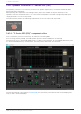
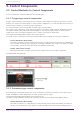
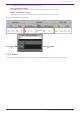
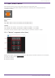
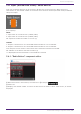
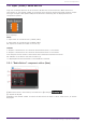
Table Of Contents
- ProVisionaire Design
- Contents
- 1. Introduction
- 2. Audio Components
- 2.1. The Difference Between Mono, Stereo, and Multi
- 2.2. How to Control Control Signals
- 2.3. Acoustic Echo Canceller (AEC)
- 2.4. Ambient Noise Compensator (ANC)
- 2.5. Audio Detector
- 2.6. Auto Gain Control (AGC)
- 2.7. Combiner: Room Combiner, Room Combiner plus Automixer
- 2.8. DCA
- 2.9. Delay
- 2.10. Dynamics: Compressor
- 2.11. Dynamics: Comp260
- 2.12. Dynamics: De-Esser
- 2.13. Dynamics: Ducker
- 2.14. Dynamics: Gate
- 2.15. Dynamics: Limiter
- 2.16. Dynamics: Paging Ducker
- 2.17. Dynamics: Program Ducker
- 2.18. Effect: Ping Pong Delay
- 2.19. Effect: REV-X
- 2.20. EQ: GEQ
- 2.21. EQ: PEQ
- 2.22. Fader
- 2.23. Feedback Suppressor: Notch FBS
- 2.24. Feedback Suppressor: Pitch Shift FBS
- 2.25. Filter: BPF
- 2.26. Filter: HPF
- 2.27. Filter: LPF
- 2.28. Input/Output: Dante In
- 2.29. Input/Output: USB In
- 2.30. Input/Output: Dante Out
- 2.31. Input/Output: USB Out
- 2.32. Input/Output: SD Card
- 2.33. Meter
- 2.34. Mixer: Delay Matrix, Matrix Mixer
- 2.35. Mixer: Dugan Automixer
- 2.36. Oscillator
- 2.37. Polarity
- 2.38. Probe
- 2.39. Router
- 2.40. Source Selector
- 2.41. Speaker Processor: Standard SPP
- 2.42. Speaker Processor: C-Series SPP (FIR)
- 3. Control Components
- 3.1. Control Methods for Control Components
- 3.2. Input (Normalized Value): Button
- 3.3. Input (Value): Button
- 3.4. Input (Normalized Value): Radio Button
- 3.5. Input (Value): Radio Button
- 3.6. Input (Normalized Value): Fader
- 3.7. Input (Value): Fader
- 3.8. Processing (Normalized Value): Logic
- 3.9. Processing (Normalized Value): NOT
- 3.10. Processing (Normalized Value): Flip-Flop
- 3.11. Processing (Normalized Value): Invert
- 3.12. Processing (Normalized Value): Compare
- 3.13. Processing (Normalized Value): Difference
- 3.14. Processing (Normalized Value): Max/Min
- 3.15. Processing (Value): Negate
- 3.16. Processing (Value): Compare
- 3.17. Processing (Value): Multi Compare
- 3.18. Processing (Value): Difference
- 3.19. Processing (Value): Max/Min
- 3.20. Processing: Delay
- 3.21. Processing: External Events
- 3.22. Processing: Suspend
- 3.23. Processing: Router
- 3.24. Controller: GPI In
- 3.25. Controller: GPI Out
- 3.26. Controller: Scheduler
- 3.27. Parameter Set
- 3.28. Snapshot

3. Control Components
3.1. Control Methods for Control Components
Control components can be divided into three broad types.
3.1.1. Trigger-type control components:
Trigger-type components are used primarily to output control signals through the operation of knobs,
buttons, etc. and to use those signals to control other components, or to execute desired processes by
sending control signals to processing-type components.
(It is also possible to move a controller by inputting a control signal.)
For trigger-type components, there are three types of controllers (Fader, Button, Radio Button) and
two types of data types (Value, Normalized Value) for the control signal output for each (control
signal input to the controlled component), for a total of six types of components.
The following example (Fader) explains how to use this list.
The fader control component can send continuous value control signals to the target component.
•
Control Parameter (Red outline):
The name of the port used to output the controller change notification (Output Port Name) and
the controller parameter type (Trigger/Processing). In addition, the name of the input port used
to externally control the controller (Input Port Name) is also listed.
•
Output Value (Green outline):
Data type and range of output values that are output when the controller is operated.
(Example) Fader (Normalized)
3.1.2. Processing-type control components:
Processing-type components output the result of specific processing in response to an input control
signal. The DME7 provides components for each of these process types.
The following example (NOT) explains how to use this list.
The NOT control component is a control component that inverts the input value (OFF:0, ON:1).
•
Control Parameter (Red outline):
The name of the port for input data for the Processing process (Input Port Name), the name of
the port for notification of the result of the Processing process (Output Port Name), and the
3. Control Components
122 | ProVisionaire Design Component Guide