
User Manual
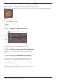
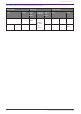
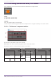
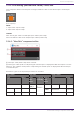
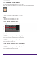
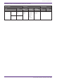
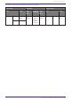
Table Of Contents
- ProVisionaire Design
- Contents
- 1. Introduction
- 2. Audio Components
- 2.1. The Difference Between Mono, Stereo, and Multi
- 2.2. How to Control Control Signals
- 2.3. Acoustic Echo Canceller (AEC)
- 2.4. Ambient Noise Compensator (ANC)
- 2.5. Audio Detector
- 2.6. Auto Gain Control (AGC)
- 2.7. Combiner: Room Combiner, Room Combiner plus Automixer
- 2.8. DCA
- 2.9. Delay
- 2.10. Dynamics: Compressor
- 2.11. Dynamics: Comp260
- 2.12. Dynamics: De-Esser
- 2.13. Dynamics: Ducker
- 2.14. Dynamics: Gate
- 2.15. Dynamics: Limiter
- 2.16. Dynamics: Paging Ducker
- 2.17. Dynamics: Program Ducker
- 2.18. Effect: Ping Pong Delay
- 2.19. Effect: REV-X
- 2.20. EQ: GEQ
- 2.21. EQ: PEQ
- 2.22. Fader
- 2.23. Feedback Suppressor: Notch FBS
- 2.24. Feedback Suppressor: Pitch Shift FBS
- 2.25. Filter: BPF
- 2.26. Filter: HPF
- 2.27. Filter: LPF
- 2.28. Input/Output: Dante In
- 2.29. Input/Output: USB In
- 2.30. Input/Output: Dante Out
- 2.31. Input/Output: USB Out
- 2.32. Input/Output: SD Card
- 2.33. Meter
- 2.34. Mixer: Delay Matrix, Matrix Mixer
- 2.35. Mixer: Dugan Automixer
- 2.36. Oscillator
- 2.37. Polarity
- 2.38. Probe
- 2.39. Router
- 2.40. Source Selector
- 2.41. Speaker Processor: Standard SPP
- 2.42. Speaker Processor: C-Series SPP (FIR)
- 3. Control Components
- 3.1. Control Methods for Control Components
- 3.2. Input (Normalized Value): Button
- 3.3. Input (Value): Button
- 3.4. Input (Normalized Value): Radio Button
- 3.5. Input (Value): Radio Button
- 3.6. Input (Normalized Value): Fader
- 3.7. Input (Value): Fader
- 3.8. Processing (Normalized Value): Logic
- 3.9. Processing (Normalized Value): NOT
- 3.10. Processing (Normalized Value): Flip-Flop
- 3.11. Processing (Normalized Value): Invert
- 3.12. Processing (Normalized Value): Compare
- 3.13. Processing (Normalized Value): Difference
- 3.14. Processing (Normalized Value): Max/Min
- 3.15. Processing (Value): Negate
- 3.16. Processing (Value): Compare
- 3.17. Processing (Value): Multi Compare
- 3.18. Processing (Value): Difference
- 3.19. Processing (Value): Max/Min
- 3.20. Processing: Delay
- 3.21. Processing: External Events
- 3.22. Processing: Suspend
- 3.23. Processing: Router
- 3.24. Controller: GPI In
- 3.25. Controller: GPI Out
- 3.26. Controller: Scheduler
- 3.27. Parameter Set
- 3.28. Snapshot

3.14. Processing (Normalized Value): Max/Min
This component detects and outputs the largest/smallest value of the values input from multiple
ports.
(For 2 inputs)
INPUT
1: Input value 1 (0.00–1.00)
2: Input value 2 (0.00–1.00)
OUTPUT
Max: The largest value from multiple input values (0.00–1.00)
Min: The smallest value from multiple input values (0.00–1.00)
3.14.1. ”Max/Min” component editor
① The input value (0.00–1.00) can be checked.
② The largest value (0.00 to 1.00) among all channel inputs is displayed as Max and output from the
Max port. The smallest value (0.00 to 1.00) among all channel inputs is displayed as Min and output
from the Min port.
Parameter types of the input/output values for each Port
Input Value Operation Output Value
Type Range Input
Port
Name
Trigger/P
rocessing
Output
Port
Name
Type Range
Normalized 0.00–1.00 ● CH
(1,2..)
Processin
g:
Max/Min
- - - -
- - - - ● Max Normalized 0.00–1.00
- - - - ● Min Normalized 0.00–1.00
3. Control Components
ProVisionaire Design Component Guide | 143