
User Manual
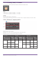
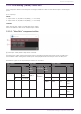
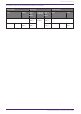
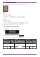
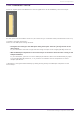
Table Of Contents
- ProVisionaire Design
- Contents
- 1. Introduction
- 2. Audio Components
- 2.1. The Difference Between Mono, Stereo, and Multi
- 2.2. How to Control Control Signals
- 2.3. Acoustic Echo Canceller (AEC)
- 2.4. Ambient Noise Compensator (ANC)
- 2.5. Audio Detector
- 2.6. Auto Gain Control (AGC)
- 2.7. Combiner: Room Combiner, Room Combiner plus Automixer
- 2.8. DCA
- 2.9. Delay
- 2.10. Dynamics: Compressor
- 2.11. Dynamics: Comp260
- 2.12. Dynamics: De-Esser
- 2.13. Dynamics: Ducker
- 2.14. Dynamics: Gate
- 2.15. Dynamics: Limiter
- 2.16. Dynamics: Paging Ducker
- 2.17. Dynamics: Program Ducker
- 2.18. Effect: Ping Pong Delay
- 2.19. Effect: REV-X
- 2.20. EQ: GEQ
- 2.21. EQ: PEQ
- 2.22. Fader
- 2.23. Feedback Suppressor: Notch FBS
- 2.24. Feedback Suppressor: Pitch Shift FBS
- 2.25. Filter: BPF
- 2.26. Filter: HPF
- 2.27. Filter: LPF
- 2.28. Input/Output: Dante In
- 2.29. Input/Output: USB In
- 2.30. Input/Output: Dante Out
- 2.31. Input/Output: USB Out
- 2.32. Input/Output: SD Card
- 2.33. Meter
- 2.34. Mixer: Delay Matrix, Matrix Mixer
- 2.35. Mixer: Dugan Automixer
- 2.36. Oscillator
- 2.37. Polarity
- 2.38. Probe
- 2.39. Router
- 2.40. Source Selector
- 2.41. Speaker Processor: Standard SPP
- 2.42. Speaker Processor: C-Series SPP (FIR)
- 3. Control Components
- 3.1. Control Methods for Control Components
- 3.2. Input (Normalized Value): Button
- 3.3. Input (Value): Button
- 3.4. Input (Normalized Value): Radio Button
- 3.5. Input (Value): Radio Button
- 3.6. Input (Normalized Value): Fader
- 3.7. Input (Value): Fader
- 3.8. Processing (Normalized Value): Logic
- 3.9. Processing (Normalized Value): NOT
- 3.10. Processing (Normalized Value): Flip-Flop
- 3.11. Processing (Normalized Value): Invert
- 3.12. Processing (Normalized Value): Compare
- 3.13. Processing (Normalized Value): Difference
- 3.14. Processing (Normalized Value): Max/Min
- 3.15. Processing (Value): Negate
- 3.16. Processing (Value): Compare
- 3.17. Processing (Value): Multi Compare
- 3.18. Processing (Value): Difference
- 3.19. Processing (Value): Max/Min
- 3.20. Processing: Delay
- 3.21. Processing: External Events
- 3.22. Processing: Suspend
- 3.23. Processing: Router
- 3.24. Controller: GPI In
- 3.25. Controller: GPI Out
- 3.26. Controller: Scheduler
- 3.27. Parameter Set
- 3.28. Snapshot

3.23. Processing: Router
Assigns an input to an output port.
One input can be output to multiple channels, but multiple inputs cannot be output to a single channel.
(For 2 inputs)
INPUT
1: Input value to channel 1
2: Input value to channel 2
Out1 In1: Switches the output of In1 to Out1 (OFF:0, ON:1) (*)
Out1 In2: Switches the output of In2 to Out1 (OFF:0, ON:1) (*)
Out1 Sel: Specifies the input signal output to Out1 (0–64) (*)
The signal is not output if 0 is specified.
Out2 In1: Switches the output of In1 to Out2 (OFF:0, ON:1) (*)
Out2 In2: Switches the output of In2 to Out2 (OFF:0, ON:1) (*)
Out2 Sel: Specifies the input signal output to Out2 (0–64) (*)
The signal is not output if 0 is specified.
OUTPUT
1: Output value from channel 1
2: Output value from channel 2
Out1 In1: Output state of In1 for Out1 (OFF:0, ON:1) (*)
Out1 In2: Output state of In2 for Out1 (OFF:0, ON:1) (*)
Out1 Sel: Specifies the input signal output to Out1 (0–64) (*)
Out2 In1: Output state of In1 for Out2 (OFF:0, ON:1) (*)
Out2 In2: Output state of In2 for Out2 (OFF:0, ON:1) (*)
Out2 Sel: Specifies the input signal output to Out2 (0–64) (*)
* is displayed when the Parameters Control PINs are checked.
3. Control Components
ProVisionaire Design Component Guide | 157