
User Manual
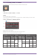
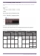
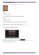
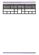
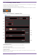
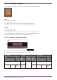
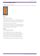
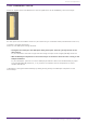
Table Of Contents
- ProVisionaire Design
- Contents
- 1. Introduction
- 2. Audio Components
- 2.1. The Difference Between Mono, Stereo, and Multi
- 2.2. How to Control Control Signals
- 2.3. Acoustic Echo Canceller (AEC)
- 2.4. Ambient Noise Compensator (ANC)
- 2.5. Audio Detector
- 2.6. Auto Gain Control (AGC)
- 2.7. Combiner: Room Combiner, Room Combiner plus Automixer
- 2.8. DCA
- 2.9. Delay
- 2.10. Dynamics: Compressor
- 2.11. Dynamics: Comp260
- 2.12. Dynamics: De-Esser
- 2.13. Dynamics: Ducker
- 2.14. Dynamics: Gate
- 2.15. Dynamics: Limiter
- 2.16. Dynamics: Paging Ducker
- 2.17. Dynamics: Program Ducker
- 2.18. Effect: Ping Pong Delay
- 2.19. Effect: REV-X
- 2.20. EQ: GEQ
- 2.21. EQ: PEQ
- 2.22. Fader
- 2.23. Feedback Suppressor: Notch FBS
- 2.24. Feedback Suppressor: Pitch Shift FBS
- 2.25. Filter: BPF
- 2.26. Filter: HPF
- 2.27. Filter: LPF
- 2.28. Input/Output: Dante In
- 2.29. Input/Output: USB In
- 2.30. Input/Output: Dante Out
- 2.31. Input/Output: USB Out
- 2.32. Input/Output: SD Card
- 2.33. Meter
- 2.34. Mixer: Delay Matrix, Matrix Mixer
- 2.35. Mixer: Dugan Automixer
- 2.36. Oscillator
- 2.37. Polarity
- 2.38. Probe
- 2.39. Router
- 2.40. Source Selector
- 2.41. Speaker Processor: Standard SPP
- 2.42. Speaker Processor: C-Series SPP (FIR)
- 3. Control Components
- 3.1. Control Methods for Control Components
- 3.2. Input (Normalized Value): Button
- 3.3. Input (Value): Button
- 3.4. Input (Normalized Value): Radio Button
- 3.5. Input (Value): Radio Button
- 3.6. Input (Normalized Value): Fader
- 3.7. Input (Value): Fader
- 3.8. Processing (Normalized Value): Logic
- 3.9. Processing (Normalized Value): NOT
- 3.10. Processing (Normalized Value): Flip-Flop
- 3.11. Processing (Normalized Value): Invert
- 3.12. Processing (Normalized Value): Compare
- 3.13. Processing (Normalized Value): Difference
- 3.14. Processing (Normalized Value): Max/Min
- 3.15. Processing (Value): Negate
- 3.16. Processing (Value): Compare
- 3.17. Processing (Value): Multi Compare
- 3.18. Processing (Value): Difference
- 3.19. Processing (Value): Max/Min
- 3.20. Processing: Delay
- 3.21. Processing: External Events
- 3.22. Processing: Suspend
- 3.23. Processing: Router
- 3.24. Controller: GPI In
- 3.25. Controller: GPI Out
- 3.26. Controller: Scheduler
- 3.27. Parameter Set
- 3.28. Snapshot

3.24. Controller: GPI In
Converts signals input from GPI IN into control signals that can be handled by the Control layer.
For the input from each GPI In connector (16 connectors), a continuous value (normalized from 0 to 1)
is output from each output port.
There are two GPI Input setting methods.
• Configure the settings in the GPI Input dialog that opens from the [Tools] button on the
device sheet.
Try this method to execute a single function using the input from a single [GPI IN] connector.
• Add the GPI Input component to the Control layer of the device sheet and set it using in the
Component Editor.
Try this method if you want to control multiple parameters/functions simultaneously by input
from a single [GPI IN] connector, or if you want to combine control components to create
complex operations.
* GPI Input is configured simultaneously by dialog setting and by the GPI Input component of the
Control layer.
3. Control Components
ProVisionaire Design Component Guide | 159