
User Manual
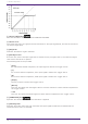
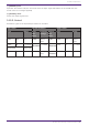
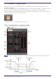
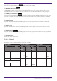
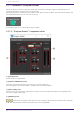
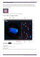
Table Of Contents
- ProVisionaire Design
- Contents
- 1. Introduction
- 2. Audio Components
- 2.1. The Difference Between Mono, Stereo, and Multi
- 2.2. How to Control Control Signals
- 2.3. Acoustic Echo Canceller (AEC)
- 2.4. Ambient Noise Compensator (ANC)
- 2.5. Audio Detector
- 2.6. Auto Gain Control (AGC)
- 2.7. Combiner: Room Combiner, Room Combiner plus Automixer
- 2.8. DCA
- 2.9. Delay
- 2.10. Dynamics: Compressor
- 2.11. Dynamics: Comp260
- 2.12. Dynamics: De-Esser
- 2.13. Dynamics: Ducker
- 2.14. Dynamics: Gate
- 2.15. Dynamics: Limiter
- 2.16. Dynamics: Paging Ducker
- 2.17. Dynamics: Program Ducker
- 2.18. Effect: Ping Pong Delay
- 2.19. Effect: REV-X
- 2.20. EQ: GEQ
- 2.21. EQ: PEQ
- 2.22. Fader
- 2.23. Feedback Suppressor: Notch FBS
- 2.24. Feedback Suppressor: Pitch Shift FBS
- 2.25. Filter: BPF
- 2.26. Filter: HPF
- 2.27. Filter: LPF
- 2.28. Input/Output: Dante In
- 2.29. Input/Output: USB In
- 2.30. Input/Output: Dante Out
- 2.31. Input/Output: USB Out
- 2.32. Input/Output: SD Card
- 2.33. Meter
- 2.34. Mixer: Delay Matrix, Matrix Mixer
- 2.35. Mixer: Dugan Automixer
- 2.36. Oscillator
- 2.37. Polarity
- 2.38. Probe
- 2.39. Router
- 2.40. Source Selector
- 2.41. Speaker Processor: Standard SPP
- 2.42. Speaker Processor: C-Series SPP (FIR)
- 3. Control Components
- 3.1. Control Methods for Control Components
- 3.2. Input (Normalized Value): Button
- 3.3. Input (Value): Button
- 3.4. Input (Normalized Value): Radio Button
- 3.5. Input (Value): Radio Button
- 3.6. Input (Normalized Value): Fader
- 3.7. Input (Value): Fader
- 3.8. Processing (Normalized Value): Logic
- 3.9. Processing (Normalized Value): NOT
- 3.10. Processing (Normalized Value): Flip-Flop
- 3.11. Processing (Normalized Value): Invert
- 3.12. Processing (Normalized Value): Compare
- 3.13. Processing (Normalized Value): Difference
- 3.14. Processing (Normalized Value): Max/Min
- 3.15. Processing (Value): Negate
- 3.16. Processing (Value): Compare
- 3.17. Processing (Value): Multi Compare
- 3.18. Processing (Value): Difference
- 3.19. Processing (Value): Max/Min
- 3.20. Processing: Delay
- 3.21. Processing: External Events
- 3.22. Processing: Suspend
- 3.23. Processing: Router
- 3.24. Controller: GPI In
- 3.25. Controller: GPI Out
- 3.26. Controller: Scheduler
- 3.27. Parameter Set
- 3.28. Snapshot

① Paging Ducker [ON] button
Switches the paging ducker function between enabled and disabled.
② TRIGGER [ON] button
If you turn this on, the audio signal level of the program source is lowered to the value specified by
the [RANGE] knob. If you turn this off, the audio signal level of the program source returns to its
original level. Set this so that it operates in tandem with the talk switch/button of the paging mic.
③ [RANGE] knob/indicator
The knob sets the audio signal level of the program source when the TRIGGER [ON] button is on. The
indicator is lit when the signal decreases to the level specified by the knob. If you attach an LED to
GPI and register the [RANGE] indicator to GPI, you’ll be able to check whether the paging mic is active.
④ [ATTACK] knob
Specifies the time over which the audio signal level of the program source decreases to the level
specified by the [RANGE] knob, starting when the TRIGGER [ON] button turns on.
⑤ [HOLD] knob
Specifies the time after which the audio signal level of the program source starts returning to the
original level after the TRIGGER [ON] button turns off.
⑥ [RELEACE] knob
Specifies the time over which the audio signal level of the program source returns to the original level
after the time specified by the [HOLD] knob.
⑦ [OUTPUT] meter
Shows the output signal level.
2.16.2. Control
Parameter types of the input/output values for each Port
Input Value Control Parameter Output Value
Type Range Input
Port
Name
Paramete
r Range
Output
Port
Name
Type Range
Value Num 0,1 ● On
OFF:0,
ON:1
● On Value Num
OFF:0,
ON:1
Value Num 0,1 ● Trigger
OFF:0,
ON:1
● Trigger Value Num
OFF:0,
ON:1
Value dB −∞–10.00 ●
Release
−∞–10.00 ●
Release
Value dB −∞–10.00
Normalized 0.00–1.00
- - - -
OFF:0,
ON:1
● Range
Indicator
Value Num 0,1
2. Audio Components
ProVisionaire Design Component Guide | 53