
User Manual
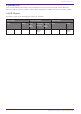
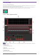
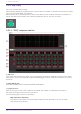
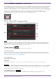
Table Of Contents
- ProVisionaire Design
- Contents
- 1. Introduction
- 2. Audio Components
- 2.1. The Difference Between Mono, Stereo, and Multi
- 2.2. How to Control Control Signals
- 2.3. Acoustic Echo Canceller (AEC)
- 2.4. Ambient Noise Compensator (ANC)
- 2.5. Audio Detector
- 2.6. Auto Gain Control (AGC)
- 2.7. Combiner: Room Combiner, Room Combiner plus Automixer
- 2.8. DCA
- 2.9. Delay
- 2.10. Dynamics: Compressor
- 2.11. Dynamics: Comp260
- 2.12. Dynamics: De-Esser
- 2.13. Dynamics: Ducker
- 2.14. Dynamics: Gate
- 2.15. Dynamics: Limiter
- 2.16. Dynamics: Paging Ducker
- 2.17. Dynamics: Program Ducker
- 2.18. Effect: Ping Pong Delay
- 2.19. Effect: REV-X
- 2.20. EQ: GEQ
- 2.21. EQ: PEQ
- 2.22. Fader
- 2.23. Feedback Suppressor: Notch FBS
- 2.24. Feedback Suppressor: Pitch Shift FBS
- 2.25. Filter: BPF
- 2.26. Filter: HPF
- 2.27. Filter: LPF
- 2.28. Input/Output: Dante In
- 2.29. Input/Output: USB In
- 2.30. Input/Output: Dante Out
- 2.31. Input/Output: USB Out
- 2.32. Input/Output: SD Card
- 2.33. Meter
- 2.34. Mixer: Delay Matrix, Matrix Mixer
- 2.35. Mixer: Dugan Automixer
- 2.36. Oscillator
- 2.37. Polarity
- 2.38. Probe
- 2.39. Router
- 2.40. Source Selector
- 2.41. Speaker Processor: Standard SPP
- 2.42. Speaker Processor: C-Series SPP (FIR)
- 3. Control Components
- 3.1. Control Methods for Control Components
- 3.2. Input (Normalized Value): Button
- 3.3. Input (Value): Button
- 3.4. Input (Normalized Value): Radio Button
- 3.5. Input (Value): Radio Button
- 3.6. Input (Normalized Value): Fader
- 3.7. Input (Value): Fader
- 3.8. Processing (Normalized Value): Logic
- 3.9. Processing (Normalized Value): NOT
- 3.10. Processing (Normalized Value): Flip-Flop
- 3.11. Processing (Normalized Value): Invert
- 3.12. Processing (Normalized Value): Compare
- 3.13. Processing (Normalized Value): Difference
- 3.14. Processing (Normalized Value): Max/Min
- 3.15. Processing (Value): Negate
- 3.16. Processing (Value): Compare
- 3.17. Processing (Value): Multi Compare
- 3.18. Processing (Value): Difference
- 3.19. Processing (Value): Max/Min
- 3.20. Processing: Delay
- 3.21. Processing: External Events
- 3.22. Processing: Suspend
- 3.23. Processing: Router
- 3.24. Controller: GPI In
- 3.25. Controller: GPI Out
- 3.26. Controller: Scheduler
- 3.27. Parameter Set
- 3.28. Snapshot

⑥ [CLEAR] button
Clears the filter settings.
⑦ [Freq.]
Displays the frequencies of the filters that were applied. Up to seven filters will be applied.
• The indicator will light when the following occurs.
◦ When a frequency is displayed
◦ When a currently-displayed frequency is rewritten
• When using FIXED, calculation will continue repeatedly even after all seven filters have been
displayed, for example to combine the frequencies that are closest to each other. However when
using DYNAMIC, if all seven filters are already displayed but new feedback is found, the filter
that was specified first and that will have the least effect on the audio quality will be
discarded, and replaced by the newly-specified filter. A filter will be discarded automatically
after a certain length of time has elapsed since it was applied.
• It is not possible to completely eliminate all feedback in all environments.
• If feedback increases when you raise a fader or the gain, and is not automatically suppressed,
lower the fader or gain to prevent the speakers from being damaged.
Performing FBS detection for the FIXED type
In order to obtain good results, you should set up the mics, speakers, and other sound equipment, and
adjust the output EQ settings before performing detection. If you want, FIXED can also be used in
conjunction with DYNAMIC.
1. Adjust the power amp output volume.
While vocalizing into the mic, gradually raise the power amp output to the volume at which the system
will be operated in actual use. In addition, clap your hands and verify that feedback does not occur.
2. Maintain silence in the space for which you want to suppress feedback.
3. Minimize the input of the mic that you want to detect.
To minimize the input, you can either adjust the input gain or use the fader to adjust the output. In
the components that you have placed, adjust the parameters of the appropriate component.
4. Click the [DETECT] button to begin detection.
5. Gradually raise the input of the mic that you want to detect.
Feedback will occur, but the DME7 will immediately detect that frequency and insert a filter.
Repeat this operation. When you have obtained a satisfactory result, click the [DETECT] button to end
detection.
If you don’t notice any result, it may be that detection has failed. Click the [CLEAR] button to
discard the detection result. If you want to make the settings once again, adjust the position of the
mics and speakers, adjust the volume, and try the above procedure once again from step 1. In some
cases, detection will not occur correctly if the overall volume is raised excessively, or if the mics and
speakers are too close, or if sound from a speaker is directly entering a mic.
The DME7 cannot detect multiple feedback points simultaneously. Slowly increasing the fader
and gain, etc. to allow the acoustic feedback to occur gradually will allow for appropriate results to be
obtained.
2. Audio Components
ProVisionaire Design Component Guide | 69