
User Manual
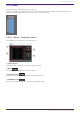
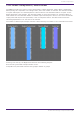
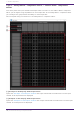
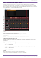
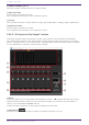
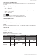
Table Of Contents
- ProVisionaire Design
- Contents
- 1. Introduction
- 2. Audio Components
- 2.1. The Difference Between Mono, Stereo, and Multi
- 2.2. How to Control Control Signals
- 2.3. Acoustic Echo Canceller (AEC)
- 2.4. Ambient Noise Compensator (ANC)
- 2.5. Audio Detector
- 2.6. Auto Gain Control (AGC)
- 2.7. Combiner: Room Combiner, Room Combiner plus Automixer
- 2.8. DCA
- 2.9. Delay
- 2.10. Dynamics: Compressor
- 2.11. Dynamics: Comp260
- 2.12. Dynamics: De-Esser
- 2.13. Dynamics: Ducker
- 2.14. Dynamics: Gate
- 2.15. Dynamics: Limiter
- 2.16. Dynamics: Paging Ducker
- 2.17. Dynamics: Program Ducker
- 2.18. Effect: Ping Pong Delay
- 2.19. Effect: REV-X
- 2.20. EQ: GEQ
- 2.21. EQ: PEQ
- 2.22. Fader
- 2.23. Feedback Suppressor: Notch FBS
- 2.24. Feedback Suppressor: Pitch Shift FBS
- 2.25. Filter: BPF
- 2.26. Filter: HPF
- 2.27. Filter: LPF
- 2.28. Input/Output: Dante In
- 2.29. Input/Output: USB In
- 2.30. Input/Output: Dante Out
- 2.31. Input/Output: USB Out
- 2.32. Input/Output: SD Card
- 2.33. Meter
- 2.34. Mixer: Delay Matrix, Matrix Mixer
- 2.35. Mixer: Dugan Automixer
- 2.36. Oscillator
- 2.37. Polarity
- 2.38. Probe
- 2.39. Router
- 2.40. Source Selector
- 2.41. Speaker Processor: Standard SPP
- 2.42. Speaker Processor: C-Series SPP (FIR)
- 3. Control Components
- 3.1. Control Methods for Control Components
- 3.2. Input (Normalized Value): Button
- 3.3. Input (Value): Button
- 3.4. Input (Normalized Value): Radio Button
- 3.5. Input (Value): Radio Button
- 3.6. Input (Normalized Value): Fader
- 3.7. Input (Value): Fader
- 3.8. Processing (Normalized Value): Logic
- 3.9. Processing (Normalized Value): NOT
- 3.10. Processing (Normalized Value): Flip-Flop
- 3.11. Processing (Normalized Value): Invert
- 3.12. Processing (Normalized Value): Compare
- 3.13. Processing (Normalized Value): Difference
- 3.14. Processing (Normalized Value): Max/Min
- 3.15. Processing (Value): Negate
- 3.16. Processing (Value): Compare
- 3.17. Processing (Value): Multi Compare
- 3.18. Processing (Value): Difference
- 3.19. Processing (Value): Max/Min
- 3.20. Processing: Delay
- 3.21. Processing: External Events
- 3.22. Processing: Suspend
- 3.23. Processing: Router
- 3.24. Controller: GPI In
- 3.25. Controller: GPI Out
- 3.26. Controller: Scheduler
- 3.27. Parameter Set
- 3.28. Snapshot

2.34. Mixer: Delay Matrix, Matrix Mixer
The DME7 provides four types of mixers: Delay Matrix, Dugan Automixer, Matrix Mixer, and Summer.
When placing this component in the design sheet, select the number of channels. The maximum number
of inputs and outputs for the Delay Matrix is 64-in/128-out. The maximum number of inputs for the
Dugan Automixer is 64 channels. The maximum number of inputs and outputs for the Matrix Mixer is
256-in/256-out. The maximum number of Summer inputs and outputs is 32-in/1-out. Since the Summer
simply mixes and outputs the input audio, it has no component editor. The illustration used in the
following explanation is for the case of 16 channels.
The number of Dante Input/Output channels is determined by the number of activated device licenses.
Starting from the top, the Dugan Automixer has the following outputs.
Discrete Out (processed sound) × number of mics
Group Mix Out (the mixed sound of each group) × number of groups
2. Audio Components
ProVisionaire Design Component Guide | 93