
User Manual
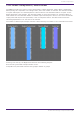
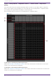
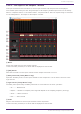
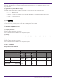
Table Of Contents
- ProVisionaire Design
- Contents
- 1. Introduction
- 2. Audio Components
- 2.1. The Difference Between Mono, Stereo, and Multi
- 2.2. How to Control Control Signals
- 2.3. Acoustic Echo Canceller (AEC)
- 2.4. Ambient Noise Compensator (ANC)
- 2.5. Audio Detector
- 2.6. Auto Gain Control (AGC)
- 2.7. Combiner: Room Combiner, Room Combiner plus Automixer
- 2.8. DCA
- 2.9. Delay
- 2.10. Dynamics: Compressor
- 2.11. Dynamics: Comp260
- 2.12. Dynamics: De-Esser
- 2.13. Dynamics: Ducker
- 2.14. Dynamics: Gate
- 2.15. Dynamics: Limiter
- 2.16. Dynamics: Paging Ducker
- 2.17. Dynamics: Program Ducker
- 2.18. Effect: Ping Pong Delay
- 2.19. Effect: REV-X
- 2.20. EQ: GEQ
- 2.21. EQ: PEQ
- 2.22. Fader
- 2.23. Feedback Suppressor: Notch FBS
- 2.24. Feedback Suppressor: Pitch Shift FBS
- 2.25. Filter: BPF
- 2.26. Filter: HPF
- 2.27. Filter: LPF
- 2.28. Input/Output: Dante In
- 2.29. Input/Output: USB In
- 2.30. Input/Output: Dante Out
- 2.31. Input/Output: USB Out
- 2.32. Input/Output: SD Card
- 2.33. Meter
- 2.34. Mixer: Delay Matrix, Matrix Mixer
- 2.35. Mixer: Dugan Automixer
- 2.36. Oscillator
- 2.37. Polarity
- 2.38. Probe
- 2.39. Router
- 2.40. Source Selector
- 2.41. Speaker Processor: Standard SPP
- 2.42. Speaker Processor: C-Series SPP (FIR)
- 3. Control Components
- 3.1. Control Methods for Control Components
- 3.2. Input (Normalized Value): Button
- 3.3. Input (Value): Button
- 3.4. Input (Normalized Value): Radio Button
- 3.5. Input (Value): Radio Button
- 3.6. Input (Normalized Value): Fader
- 3.7. Input (Value): Fader
- 3.8. Processing (Normalized Value): Logic
- 3.9. Processing (Normalized Value): NOT
- 3.10. Processing (Normalized Value): Flip-Flop
- 3.11. Processing (Normalized Value): Invert
- 3.12. Processing (Normalized Value): Compare
- 3.13. Processing (Normalized Value): Difference
- 3.14. Processing (Normalized Value): Max/Min
- 3.15. Processing (Value): Negate
- 3.16. Processing (Value): Compare
- 3.17. Processing (Value): Multi Compare
- 3.18. Processing (Value): Difference
- 3.19. Processing (Value): Max/Min
- 3.20. Processing: Delay
- 3.21. Processing: External Events
- 3.22. Processing: Suspend
- 3.23. Processing: Router
- 3.24. Controller: GPI In
- 3.25. Controller: GPI Out
- 3.26. Controller: Scheduler
- 3.27. Parameter Set
- 3.28. Snapshot

③ Channel matrix
Shows the send level and delay for each channel. The vertical axis shows the input channel, and the
horizontal axis shows the output channel. A cross-point is displayed when the cursor is placed over
this. It changes to selection mode when clicked. Press the up/down arrow keys or hold down the left
mouse button and move up or down to change the value. The numeric value can also be entered directly
by double clicking. Press the <Tab> key to move right.
When you double-click a port name display area located above or to the left of the matrix, a window
opens, allowing you to edit the name of the port.
Right-clicking on a cross-point allows the cross-point to be set on or off, the send level to be set, as
well as the ability to turn the horizontal or vertical axis with the cross-point on or off and setting its
send level. The settings of a horizontal/vertical axis can be copy & pasted to another
horizontal/vertical axis, or the display can be changed to a bar graph. The following choices are
provided.
•
[One Input to All Outputs]
Opens the One Input to All Outputs window.
•
[All Inputs to One Output]
Opens the All Inputs to One Output window.
•
[On]
Turns the cross-point ON.
•
[Off]
Turns the cross-point OFF.
•
[Nominal]
Sets the cross-point’s send level to 0 dB.
•
[-3dB]
Sets the cross-point send level to –3 dB.
•
[-6dB]
Sets the cross-point send level to –6 dB.
•
[Minimum]
Sets the cross-point send level to −∞ dB.
2. Audio Components
ProVisionaire Design Component Guide | 95