
User Manual
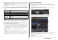
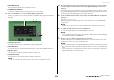
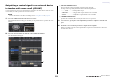
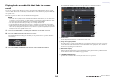
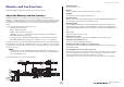
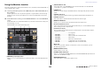
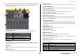
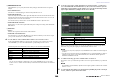
Table Of Contents
- How to Use This Reference Manual
- Contents
- Function Tree
- SELECTED CHANNEL section
- Centralogic section
- Input and output patching
- Input channels
- Signal flow for input channels
- Specifying the channel name, icon and channel color
- Making HA (Head Amp) settings
- Sending a signal from an input channel to the STEREO/MONO buses
- Sending a signal from an input channel to a MIX/ MATRIX bus
- Correcting delay between channels (Input Delay)
- Channel library operations
- Output channels
- EQ and Dynamics
- Grouping and linking
- Scene memory
- About scene memories
- Using scene memories
- Editing scene memories
- Using the Global Paste function
- Using the Focus function
- Using the Recall Safe function
- Using the Fade function
- Outputting a control signal to an external device in tandem with scene recall (GPI OUT)
- Playing back an audio file that links to a scene recall
- Using Preview mode
- Monitor and Cue functions
- Talkback and Oscillator
- Meters
- Graphic EQ, effects, and Premium Rack
- I/O device and external head amp
- MIDI
- User settings (Security)
- Recorder
- Help function
- Other functions
- About the SETUP screen
- Word clock and slot settings
- Using cascade connections
- Basic settings for MIX buses and MATRIX buses
- Switching the entire phantom power supply on/ off
- Specifying the brightness of the touch screen, LEDs, channel name displays, and lamps
- Setting the date and time of the internal clock
- Setting the network address
- Initializing the unit to factory default settings
- Adjusting the detection point of the touch screen (Calibration function)
- Adjusting the faders (Calibration function)
- Fine-tuning the input and output gain (Calibration function)
- Adjusting the channel color (Calibration function)
- Adjusting the brightness of the channel name display
- Adjusting the contrast of the channel name display
- Dante audio network settings
- Using GPI (General Purpose Interface)
- Appendices
- EQ Library List
- DYNAMICS Library List
- Dynamics Parameters
- Effect Type List
- Effects Parameters
- Premium Rack Processor Parameters
- Effects and tempo synchronization
- Parameters that can be assigned to control changes
- NRPN parameter assignments
- Mixing parameter operation applicability
- Functions that can be assigned to USER DEFINED keys
- Functions that can be assigned to USER DEFINED knobs
- Functions that can be assigned to the assignable encoders
- MIDI Data Format
- Warning/Error Messages
- Electrical characteristics
- Mixer Basic Parameters
- M IDI Implementation Chart
- Index

Monitor and Cue functions
Reference Manual
100
0 MONITOR DELAY field
This field enables you to specify the monitor delay setting by which the monitor out signal is
delayed.
• AUTO BYPASS button
Turn this on to automatically bypass monitor delay when the cue is on.
• MONITOR DELAY knob
Adjusts the delay time for the monitor signal. The delay time is shown above the knob in ms units,
and below the knob in units of the currently selected scale. However if the scale is set to ms, the
delay time value is not shown above the knob.
Press this knob and you will be able to use the multifunction knob to adjust the value.
• MONITOR DELAY ON button
If this button is on, the monitor signal will be delayed according to the setting of the MONITOR
DELAY knob.
A Meter field
• Meters
Indicates the output level of the monitor L/R/C channels.
• MONITOR OUT PATCH button
Press this button to open the PORT SELECT popup window, in which you can select an output
port to patch to the monitor out L/R/C channels.
4. Use the buttons of the SOURCE SELECT field to select a monitor source.
In the SOURCE SELECT field you can select only one monitor source. However, if you have
selected DEFINE, you can use the ASSIGN field to specify multiple monitor sources.
The following table shows the monitor sources that you can select in the ASSIGN field.
NOTE
You can select a maximum of eight monitor sources in the ASSIGN field. If you select eight
monitor sources, no further selections will be possible. Please turn off the buttons for unneeded
sources.
5. To specify a port as the output destination for monitor signals L, C, and R, press
one of the MONITOR OUT PATCH buttons (L/R/C) in the meter field to open the
PORT SELECT popup window. In this window, choose from the following monitor
signal output destinations (multiple selections are allowed).
When you have selected an output port, press the CLOSE button to close the popup window.
In the same way, specify the output ports for MONITOR OUT L, R, and C.
NOTE
• If desired, you can specify output ports only for MONITOR OUT L and R to monitor through two
speakers.
• If you have not specified an output port for MONITOR OUT C, selecting the MONO (C) button or
LCR button as the monitor source will automatically cause the MONO channel signal to be
distributed to MONITOR OUT L/R.
6. To enable monitoring, press the OUTPUT button to turn it on.
The monitor source you selected in step 4 will be sent to the output destination you specified in
step 5.
NOTE
The PHONES Out jack will always output the monitor signal, regardless of whether the OUTPUT
button is on or off.
7. To control the monitor fader, press the Bank Select [STEREO] key in the Centralogic
section, and then operate the monitor fader.
MIX 1–24 Output signals of MIX channels 1–24
MTRX 1–8 MATRIX buses 1–8 output signals
STEREO STEREO L/R channel output signals
MONO (C) MONO channel output signal
OMNI 1–2 – OMNI 7–8 OMNI IN jacks 1–8 input signals (per two channels)
PB OUT Recorder’s PLAYBACK OUT signals
DANTE 1–64 Output channels 1–64 to audio network
OMNI1–8 OMNI OUT jacks 1–8
DIGI OUT L/R DIGITAL OUT jack on the CL unit
SLOT1–1 – SLOT3–16 Output channels 1–16 of an I/O card installed in slots 1–3