
User Manual
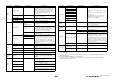
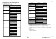
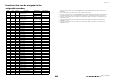
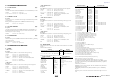
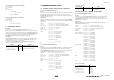
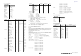
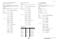
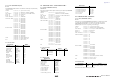
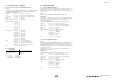
Table Of Contents
- How to Use This Reference Manual
- Contents
- Function Tree
- SELECTED CHANNEL section
- Centralogic section
- Input and output patching
- Input channels
- Signal flow for input channels
- Specifying the channel name, icon and channel color
- Making HA (Head Amp) settings
- Sending a signal from an input channel to the STEREO/MONO buses
- Sending a signal from an input channel to a MIX/ MATRIX bus
- Correcting delay between channels (Input Delay)
- Channel library operations
- Output channels
- EQ and Dynamics
- Grouping and linking
- Scene memory
- About scene memories
- Using scene memories
- Editing scene memories
- Using the Global Paste function
- Using the Focus function
- Using the Recall Safe function
- Using the Fade function
- Outputting a control signal to an external device in tandem with scene recall (GPI OUT)
- Playing back an audio file that links to a scene recall
- Using Preview mode
- Monitor and Cue functions
- Talkback and Oscillator
- Meters
- Graphic EQ, effects, and Premium Rack
- I/O device and external head amp
- MIDI
- User settings (Security)
- Recorder
- Help function
- Other functions
- About the SETUP screen
- Word clock and slot settings
- Using cascade connections
- Basic settings for MIX buses and MATRIX buses
- Switching the entire phantom power supply on/ off
- Specifying the brightness of the touch screen, LEDs, channel name displays, and lamps
- Setting the date and time of the internal clock
- Setting the network address
- Initializing the unit to factory default settings
- Adjusting the detection point of the touch screen (Calibration function)
- Adjusting the faders (Calibration function)
- Fine-tuning the input and output gain (Calibration function)
- Adjusting the channel color (Calibration function)
- Adjusting the brightness of the channel name display
- Adjusting the contrast of the channel name display
- Dante audio network settings
- Using GPI (General Purpose Interface)
- Appendices
- EQ Library List
- DYNAMICS Library List
- Dynamics Parameters
- Effect Type List
- Effects Parameters
- Premium Rack Processor Parameters
- Effects and tempo synchronization
- Parameters that can be assigned to control changes
- NRPN parameter assignments
- Mixing parameter operation applicability
- Functions that can be assigned to USER DEFINED keys
- Functions that can be assigned to USER DEFINED knobs
- Functions that can be assigned to the assignable encoders
- MIDI Data Format
- Warning/Error Messages
- Electrical characteristics
- Mixer Basic Parameters
- M IDI Implementation Chart
- Index

Appendices
Reference Manual
270
4.8 FUNCTION CALL – CHANNEL –
4.8.1 Pair ON/OFF Trigger Format (PARAMETER CHANGE)
Receive
Data will be received when [PARAMETER CHANGE Rx] is on and the Device number
of both [Rx CH] and SUB STATUS are matched. The data will be echoed when
[PARAMETER CHANGE ECHO] is on.
4.8.2 Module Name
*1) 0 :CH1 - 71:CH72
256 :MIX 1 - 279:MIX 24
512 :MATRIX 1 - 519: MATRIX 8
4.9 LEVEL METER DATA
4.9.1 Format (PARAMETER CHANGE)
When transmission is enabled by receiving Request for Level Meter, the corresponding
metering data will be sent in every 50 millisecond for 10 seconds. If metering
information is expected to be continuously sent, Request is needed to be sent in at least
every 10 seconds.
Receive
The data will be echoed when [PARAMETER CHANGE ECHO] is ON.
Transmission
When transmission is enabled by receiving Request, the corresponding metering data
will be sent in constant interval for a given period of time (The interval and time will
vary depending on devices). When rebooted or port setting is changed, the
transmission will be disabled.
When [PARAMETER CHANGE ECHO] is on, the message will be sent as it is.
4.9.2 Format (PARAMETER REQUEST)
Receive
Data will be received when [PARAMETER CHANGE Rx] is on and the Device number
of both [Rx CH] and SUB STATUS are matched. The data will be echoed when
[PARAMETER CHANGE ECHO] is on. the corresponding metering data will be sent
via [Rx CH] in constant interval for a given period of time (The interval and time will
vary depending on devices).
When Address UL = 0x7F is received, all metering data transmission will be
immediately stopped [disabled].
Transmission
When [PARAMETER CHANGE ECHO] is on, the message will be sent as it is.
STATUS 11110000 F0
System exclusive message
ID No. 01000011 43
Manufacture’s ID number (YAMAHA)
SUB STATUS 0001nnnn 1n
n=0-15 (Device number=MIDI Channel)
GROUP ID 00111110 3E
Digital mixer
MODEL ID 00010010 19
CL Series
DATA CATEGORY 00000000 00
OTHER DATA
FUNCTION NAME 01000011 "C"
01101000 "h"
01101100 "l"
01010000 "P"
01101001 "i"
01110010 "r"
01000011 "C"
01110000 "p"
MODULE NAME 0mmmmmmm mm
(ASCII CODE)
0mmmmmmm mm
(ASCII CODE)
0mmmmmmm mm
(ASCII CODE)
0mmmmmmm mm
(ASCII CODE)
0mmmmmmm mm
(ASCII CODE)
0mmmmmmm mm
(ASCII CODE)
0mmmmmmm mm
(ASCII CODE)
0mmmmmmm mm
(ASCII CODE)
DATA 0sssssss sh
Source Channel Number H *1)
0sssssss sl
Source Channel Number L *1)
0ddddddd dh
Destination Channel Number H *1)
0ddddddd dl
Destination Channel Number L *1)
EOX 11110111 F7
End of exclusive
Module Name
Pair On (with Copy) “PAIRONCP”
Pair On (with Reset Both) “PAIRONRS”
Pair Off “PAIROFF_”
STATUS 11110000 F0
System exclusive message
ID No. 01000011 43
Manufacture’s ID number (YAMAHA)
SUB STATUS 0001nnnn 1n
n=0-15 (Device number=MIDI Channel)
GROUP ID 00111110 3E
Digital mixer
MODEL ID 00010010 19
CL Series
DATA CATEGORY 00100001 21
REMOTE LEVEL METER
DATA 0mmmmmmm mm
ADDRESS UL
0mmmmmmm mm
ADDRESS LU
0mmmmmmm mm
ADDRESS LL
0ddddddd dd
Data1
::
EOX 11110111 F7
End of exclusive
STATUS 11110000 F0
System exclusive message
ID No. 01000011 43
Manufacture’s ID number (YAMAHA)
SUB STATUS 0011nnnn 3n
n=0-15 (Device number=MIDI Channel)
GROUP ID 00111110 3E
Digital mixer
MODEL ID 00010010 19
CL Series
DATA CATEGORY 00100001 21
REMOTE LEVEL METER
DATA 0mmmmmmm mm
ADDRESS UL
0mmmmmmm mm
ADDRESS LU
0mmmmmmm mm
ADDRESS LL
0ccccccc ch
Count H
0ccccccc cl
Count L
EOX 11110111 F7
End of exclusive