
User Manual
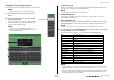
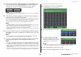
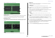
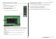
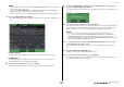
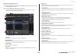
Table Of Contents
- How to Use This Reference Manual
- Contents
- Function Tree
- SELECTED CHANNEL section
- Centralogic section
- Input and output patching
- Input channels
- Signal flow for input channels
- Specifying the channel name, icon and channel color
- Making HA (Head Amp) settings
- Sending a signal from an input channel to the STEREO/MONO buses
- Sending a signal from an input channel to a MIX/ MATRIX bus
- Correcting delay between channels (Input Delay)
- Channel library operations
- Output channels
- EQ and Dynamics
- Grouping and linking
- Scene memory
- About scene memories
- Using scene memories
- Editing scene memories
- Using the Global Paste function
- Using the Focus function
- Using the Recall Safe function
- Using the Fade function
- Outputting a control signal to an external device in tandem with scene recall (GPI OUT)
- Playing back an audio file that links to a scene recall
- Using Preview mode
- Monitor and Cue functions
- Talkback and Oscillator
- Meters
- Graphic EQ, effects, and Premium Rack
- I/O device and external head amp
- MIDI
- User settings (Security)
- Recorder
- Help function
- Other functions
- About the SETUP screen
- Word clock and slot settings
- Using cascade connections
- Basic settings for MIX buses and MATRIX buses
- Switching the entire phantom power supply on/ off
- Specifying the brightness of the touch screen, LEDs, channel name displays, and lamps
- Setting the date and time of the internal clock
- Setting the network address
- Initializing the unit to factory default settings
- Adjusting the detection point of the touch screen (Calibration function)
- Adjusting the faders (Calibration function)
- Fine-tuning the input and output gain (Calibration function)
- Adjusting the channel color (Calibration function)
- Adjusting the brightness of the channel name display
- Adjusting the contrast of the channel name display
- Dante audio network settings
- Using GPI (General Purpose Interface)
- Appendices
- EQ Library List
- DYNAMICS Library List
- Dynamics Parameters
- Effect Type List
- Effects Parameters
- Premium Rack Processor Parameters
- Effects and tempo synchronization
- Parameters that can be assigned to control changes
- NRPN parameter assignments
- Mixing parameter operation applicability
- Functions that can be assigned to USER DEFINED keys
- Functions that can be assigned to USER DEFINED knobs
- Functions that can be assigned to the assignable encoders
- MIDI Data Format
- Warning/Error Messages
- Electrical characteristics
- Mixer Basic Parameters
- M IDI Implementation Chart
- Index

Grouping and linking
Reference Manual
71
Linking the desired input channels
This section explains how to link specific parameters of input channels.
NOTE
Channel link settings are saved as part of the scene.
1. In the Function Access Area, press the CH JOB
button.
2. Press the CH LINK button to open the CH LINK
MODE popup window.
In this popup window you can view the channels that are
linked and specify the parameters that will be linked. The
window includes the following items.
NOTE
You can also access this window by simultaneously
pressing and then releasing the [SEL] keys of two or more
channels that will be linked.
1 Channel display field
When you create a link group, the corresponding channels will be highlighted. If there are two or
more link groups, each group is shown in a different color.
NOTE
Left and right of the ST IN channel are always linked.
2 LINK PARAMETER field
Use the buttons in this field to select the parameters that you want to link. You can do this
independently for each link group.
3 SEND PARAMETER field
If you have turned on the MIX ON, MIX SEND, MATRIX ON, or MATRIX send buttons in the
LINK PARAMETER field, use the buttons in this field to specify the send-destination bus(es).
NOTE
In the case of the CL3/CL1, faders that do not exist on those models will not be shown.
3. Use the buttons in the LINK PARAMETER field to select the parameter(s) that will
be linked (multiple selections are allowed).
The table below lists the parameters you can select in the LINK PARAMETER field.
NOTE
• If you link Dynamics 1 or 2 for two or more input channels, the parameter values will be linked,
but the key-in signals are not linked. For details about dynamics, see “EQ and Dynamics” on
page 56.
• If you turn on the EQ button or DYNAMICS 1/2 button, library recall operations will also be linked.
• The HA analog gain setting and the fader operation will be linked and will maintain the same
relative level difference between the channels.
CH LINK button
2
1
3
HA Head amp settings
HPF HPF settings
DIGITAL GAIN Digital gain settings
EQ EQ settings
DYNAMICS 1, 2 Dynamics 1 and 2 settings
INSERT Insert settings
DIRECT OUT Direct Out settings
MIX SEND Send levels of signals sent to MIX buses
MIX ON On/off status of signals sent to MIX buses
MATRIX SEND Send levels of signals sent to MATRIX buses
MATRIX ON On/off status of signals sent to MATRIX buses
FADER Fader operations
DCA DCA group assignment
CH ON Channel on/off
MUTE Mute group assignment
TO STEREO On/off status of signals sent to STEREO/MONO buses
DELAY Channel delay settings