
User Manual
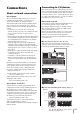
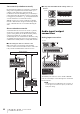
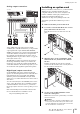
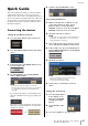
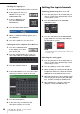
Table Of Contents
- Contents
- PRECAUTIONS
- Introduction
- An overview of the CL series
- Controls and functions
- Touch screen
- Basic operation of the CL series
- Connections
- Setup
- Quick Guide
- Connecting the devices
- Setting the input channels
- Applying EQ/dynamics
- Setting the output channels
- Using GEQ
- Applying effects
- Changing the patch settings
- Grouping and linking
- Setting a custom fader bank
- Using talkback
- Routing the oscillator to an output channel
- Using scene memories
- Recording and playing audio using a USB flash drive
- Saving and loading the unit settings
- Other functions
- Troubleshooting
- Installing the MBCL meter bridge (option)
- Specifications
- Dimensions
- Index
- Block Diagram
- Level Diagram

Connections
Owner’s Manual
32
Star network (redundant network)
In a star network, each device is connected to a central hub.
Using a GbE-compatible network switch enables you to
configure a wide-band, large-scale network. We
recommend a network switch that gives you the ability to
control and monitor the network (such as QoS, the ability
to assign priority to data flows - e.g., clock synchronization
or audio transmission on certain data circuits).
With this topology, it is usual to configure a redundant
network so that even if an unexpected network problem
occurs, communication can occur without affecting the
audio.
About redundant networks
A redundant network consists of two circuits, a primary
circuit and a secondary circuit. Normally, the network
operates on the primary circuit. However, if the primary
connection is broken, the secondary circuit will
automatically take over communications. Therefore, using
a redundant network with a star topology would increase
communication stability relative to a daisy chain network.
■ Connecting I/O devices to the CL series
Make connections as shown below using the Dante
connectors of the CL series and the I/O devices, and set the
rotary switches and DIP switches of the I/O devices.
■ Rotary switch and DIP switch settings of the I/O
devices
Audio input/output
connections
Analog input connections
The INPUT jacks on the I/O devices and the OMNI IN
jacks are used mainly to connect microphones or monaural
line-level devices.
NOTE
In the default state, the OMNI IN jacks are not patched. To
use the signals connected here as inputs, you will need to
make patch settings.
CL5
SECONDARY
SECONDARY
SECONDARY
PRIMARY
PRIMARY
PRIMARY
Rio3224-D
(ID#1)
Rio3224-D
(ID#2)
0
1
2
3
4
5
6
7
8
9
A
B
C
D
E
F
0
1
2
3
4
5
6
7
8
9
A
B
C
D
E
F
Network switch
Network switch
(ID#1)
(ID#2)
1 2 3 4 5 6 7 8
ON
1 2 3 4 5 6 7 8
ON
0
1
2
3
4
5
6
7
8
9
A
B
C
D
E
F
0
1
2
3
4
5
6
7
8
9
A
B
C
D
E
F
0
1
2
3
4
5
6
7
8
9
A
B
C
D
E
F
Rio3224-D
CL series