
User Manual


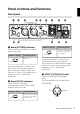

Table Of Contents
- PRECAUTIONS
- Contents
- Introduction
- Main Features
- Panel Controls and Functions
- Before Using This Product
- Basic Operations
- How to Connect via Dante
- Attaching the Cable Hook
- Attaching the Rubber Feet
- Installing in a Rack
- Restoring the Factory Default Settings (Initialization)
- Messages
- General Specifications
- Dimensions

RUio16-D Owner’s Manual
9
Panel Controls and Functions
Front panel
1 Dante [SYSTEM] indicators
These indicators show the operating
status of this unit.
An abnormality has occurred if you
have turned on the power but the
green indicator is dark and the red
indicator is either lit or flashing. If this
happens, refer to “Messages”
(page 20).
2 Dante [SYNC] indicators
These indicators show the
synchronization status of the Dante
network and of this unit.
An abnormality has occurred if you
have turned on the power but the
green indicator is dark and the orange
indicator is either lit or flashing. If this
happens, refer to “Messages”
(page 20).
3 INPUT [CH15]/[CH16] jacks
These are XLR-type analog input
jacks.
The jack polarities are shown below
(IEC 60268).
1 2 5 6 7 8 9
@ # $
3
!)
4
Indicator display Operating status
Normal
Indicator display Operating status
The unit is functioning
correctly as the word
clock follower.
Lights up green
Lights up green
The unit is functioning
correctly as the word
clock leader.
Indicator display Operating status
Flashes green
Hot Ground
Cold