
User Manual
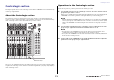

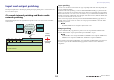
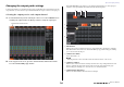
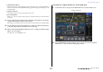
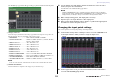
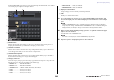
Table Of Contents
- How to Use This Reference Manual
- Contents
- Function Tree
- SELECTED CHANNEL section
- Centralogic section
- Input and output patching
- Input channels
- Signal flow for input channels
- Specifying the channel name, icon and channel color
- Making HA (Head Amp) settings
- Sending a signal from an input channel to the STEREO/MONO buses
- Sending a signal from an input channel to a MIX/ MATRIX bus
- Correcting delay between channels (Input Delay)
- Channel library operations
- Output channels
- EQ and Dynamics
- Grouping and linking
- Scene memory
- About scene memories
- Using scene memories
- Editing scene memories
- Using the Global Paste function
- Using the Focus function
- Using the Recall Safe function
- Using the Fade function
- Outputting a control signal to an external device in tandem with scene recall (GPI OUT)
- Playing back an audio file that links to a scene recall
- Using Preview mode
- Monitor and Cue functions
- Talkback and Oscillator
- Meters
- Graphic EQ, effects, and Premium Rack
- I/O device and external head amp
- MIDI
- User settings (Security)
- Recorder
- Help function
- Other functions
- About the SETUP screen
- Word clock and slot settings
- Using cascade connections
- Basic settings for MIX buses and MATRIX buses
- Switching the entire phantom power supply on/ off
- Specifying the brightness of the touch screen, LEDs, channel name displays, and lamps
- Setting the date and time of the internal clock
- Setting the network address
- Initializing the unit to factory default settings
- Adjusting the detection point of the touch screen (Calibration function)
- Adjusting the faders (Calibration function)
- Fine-tuning the input and output gain (Calibration function)
- Adjusting the channel color (Calibration function)
- Adjusting the brightness of the channel name display
- Adjusting the contrast of the channel name display
- Dante audio network settings
- Using GPI (General Purpose Interface)
- Appendices
- EQ Library List
- DYNAMICS Library List
- Dynamics Parameters
- Effect Type List
- Effects Parameters
- Premium Rack Processor Parameters
- Effects and tempo synchronization
- Parameters that can be assigned to control changes
- NRPN parameter assignments
- Mixing parameter operation applicability
- Functions that can be assigned to USER DEFINED keys
- Functions that can be assigned to USER DEFINED knobs
- Functions that can be assigned to the assignable encoders
- MIDI Data Format
- Warning/Error Messages
- Electrical characteristics
- Mixer Basic Parameters
- M IDI Implementation Chart
- Index

Input and output patching
Reference Manual
19
The CH SELECT popup window will appear. This popup window includes the following items.
1 Category select list
Selects the category of channel shown in the popup window. The categories correspond to the
following channels. They vary depending on the output port type.
• MIX/MATRIX.................................. MIX 1–MIX 24, MATRIX 1–MATRIX 8
• ST/MONO/MONI/CUE ................. STEREO L, STEREO R, MONO(C), MONI L, MONI R,
MONI C, CUE L, CUE R
• DIRECT OUT 1–32......................... CH1–CH32 Direct Outs
• DIRRECT OUT 33–64.................... CH33–CH64 Direct Outs
• DIRECT OUT 65–72 ...................... CH65–CH72 Direct Outs
• INSERT OUT 1–32.......................... CH1–CH32 Insert-outs
• INSERT OUT 33–64 ....................... CH33–CH64 Insert-outs
• INSERT OUT 65–72 ....................... CH65–CH72 Insert-outs
• INSERT OUT MIX/MATRIX ....... Insert-outs for MIX1-MIX24, MATRIX 1-MATRIX8
• INSERT OUT ST/MONO .............. Insert-outs for STEREO L, STEREO R, and MONO (C)
• CASCADE MIX/MATRIX............. MIX1–MIX24, MATRIX1–MATRIX8
• CASCADE ST/MONO/CUE.......... STEREO L, STEREO R, MONO(C), CUE L, CUE R
NOTE
In the case of the CL3/CL1, channels that do not exist on those models will not be shown.
2 Channel select buttons
Select the channel to be assigned to the output port you selected in step 3.
5. Use the channel select tabs and the channel select buttons to select the source
channel, and press the CLOSE button.
You will return to the OUTPUT PORT popup window.
NOTE
If PATCH CONFIRMATION is ON, a confirmation dialog box will appear when you attempt to
change the patch settings. If STEAL PATCH CONFIRMATION is ON, a confirmation dialog box
will appear when you attempt to change a location that is already patched elsewhere.
6. Make settings for delay, phase, and output gain as necessary.
7. Repeat steps 3–6 to assign channels to other output ports.
8. When you have finished making settings, click the “x” symbol in the upper right of
the window to return to the previous screen.
Changing the input patch settings
This section explains how to change the patching of each input channel.
1. Use the Bank Select keys in the Centralogic section to access the OVERVIEW screen
for the input channel to which you want to assign the input source.
2. In the top part of the screen, press the channel number/channel name field to
access the PATCH/NAME popup window.
1
2