
Service manual


1
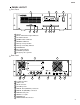
5 6 7 8 9 10 11
12 13 12
14 15 16 17 18 19 20 21
2 3 4
1
Air Inlet
2
INPUT and OUTPUT signal indicators
3
FS LOCK indicators
4
POWER switch & indicator
5
MEMORY CARD slot
6
Memory card eject button
7
Memory card activity indicator
8
CD-ROM drive
9
Disc activity indicator
10
CD-ROM eject button
11
Emergency disc eject hole
12
Cooling fan outlets
13
SLOTs 1 & 2
14
AC IN connector
15
Grounding screw
16
DIGITAL OUT (AES/EBU) connectors
17
DIGITAL IN (AES/EBU) connectors
18
MIDI IN & OUT ports
19
SERIAL 1 & 2 ports
20
REMOTE port
21
WORD CLOCK IN connector
PANEL LAYOUT
SREV1
4
Rear Panel
Front Panel