
User Manual

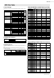
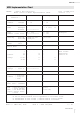


Table Of Contents

reface Data List
6
reface DX
reface DX
(1) Coverage
The specifications described herein specify transmission and reception of MIDI data of the reface DX.
(2) Compliance
The specifications described herein comply to the following standards:
• MIDI 1.0
(3) TRANSMIT/RECEIVE DATA
(3-1) CHANNEL VOICE MESSAGES
(3-1-1) NOTE OFF
STATUS 1000nnnn(8nH) n = 0 - 15 CHANNEL NUMBER
NOTE No. 0kkkkkkk k = 0 (C-2) - 127 (G8)
VELOCITY 0vvvvvvv v: ignored
Receive only
(3-1-2) NOTE ON/OFF
STATUS 1001nnnn(9nH) n = 0 - 15 CHANNEL NUMBER
NOTE NUMBER 0kkkkkkk k = 0 (C-2) - 127 (G8)
VELOCITY NOTE ON 0vvvvvvv(v≠0)
NOTE OFF 0vvvvvvv(v=0)
(3-1-3) CONTROL CHANGE
STATUS 1011nnnn(BnH) n = 0 - 15 CHANNEL NUMBER
CONTROL NUMBER 0ccccccc
CONTROL VALUE 0vvvvvvv
*TRANSMITTED CONTROL NUMBER
c = 64 SUSTAIN SWITCH ; v = 0 - 127 *1
*1 When Sustain is set to “FC4/5,” operating the foot switch transmits only values of 0 (off) or 127 (on).
*RECEIVED CONTROL NUMBER
c = 1 MODULATION ; v = 0 - 127
c = 7 VOLUME ; v = 0 - 127
c = 11 EXPRESSION ; v = 0 - 127
c = 64 SUSTAIN SWITCH ; v = 0 - 127
When MIDI Control Mode is turned on, Control Change numbers are assigned in order that voice parameter
changes made using controllers on the front panel can be controlled via MIDI.
See the following Control Change Table.
(3-1-4) PROGRAM CHANGE
STATUS 1100nnnn(CnH) n = 0 - 15 CHANNEL NUMBER
PROGRAM NUMBER 0ppppppp p = 0 - 31
Bank1-1 … 8 0 - 7
Bank2-1 … 8 8 - 15
Bank3-1 … 8 16 - 23
Bank4-1 … 8 24 - 31
(3-1-5) PITCH BEND CHANGE
STATUS 1110nnnn(EnH) n = 0 - 15 CHANNEL NUMBER
LSB 0vvvvvvv PITCH BEND CHANGE LSB
MSB 0vvvvvvv PITCH BEND CHANGE MSB
(3-2) CHANNEL MODE MESSAGES
STATUS 1011nnnn(BnH) n = 0 - 15 CHANNEL NUMBER
CONTROL NUMBER 0ccccccc c = CONTROL NUMBER
CONTROL VALUE 0vvvvvvv v = DATA VALUE
(3-2-1) ALL SOUND OFF (CONTROL NUMBER = 78H , DATA VALUE = 0)
All the sounds currently played including the channel messages such as note-on and hold-on in a certain chan-
nel are muted when receiving this message.
(3-2-2) RESET ALL CONTROLLERS (CONTROL NUMBER = 79H , DATA VALUE = 0)
Resets the values set for the following controllers.
PITCH BEND CHANGE 0 (center)
MODULATION 0 (minimum)
EXPRESSION 127 (maximum)
SUSTAIN SWITCH 0 (off)
(3-2-3) ALL NOTE OFF (CONTROL NUMBER = 7BH , DATA VALUE = 0)
All the notes currently set to on in certain channel(s) are muted when receiving this message.
However, if Sustain is on, notes will continue sounding until these are turned off.
(3-2-4) OMNI MODE OFF (CONTROL NUMBER = 7CH , DATA VALUE = 0)
Performs the same function as when receiving ALL NOTES OFF.
Sets RECEIVE CHANNEL to channel 1.
(3-2-5) OMNI MODE ON (CONTROL NUMBER = 7DH , DATA VALUE = 0)
Performs the same function as when receiving ALL NOTES OFF.
Sets RECEIVE CHANNEL to all.
(3-2-6) MONO (CONTROL NUMBER = 7EH , DATA VALUE = 0..16)
Performs the same function as when receiving ALL SOUNDS OFF.
Sets MONO/POLY to mono-full.
(3-2-7) POLY (CONTROL NUMBER = 7FH , DATA VALUE = 0)
Performs the same function as when receiving ALL SOUNDS OFF.
Sets MONO/POLY to poly.
(3-3) SYSTEM REAL TIME MESSAGES
(3-3-1) ACTIVE SENSING
STATUS 11111110(FEH)
Transmitted at every 200 msec.
Once this code is received, the instrument starts sensing.
When no status nor data is received for over approximately 350 ms, MIDI receiving buffer will be cleared, and
the sounds currently played is forcibly turned off.
(3-3-2) TIMING CLOCK
STATUS 11111000(F8H)
When received via MIDI IN or USB-MIDI IN, the instrument automatically switches to external synchronization.
to the internal clock.
If no signal is received for 3 seconds, it switches back to the internal clock.
(3-3-3) START
STATUS 11111010(FAH)
(3-3-4) CONTINUE
STATUS 11111011(FBH)
Receive only
(3-3-5) STOP
STATUS 11111100(FCH)
(3-4) SYSTEM EXCLUSIVE MESSAGE
(3-4-1) UNIVERSAL NON REALTIME MESSAGE
(3-4-1-1) IDENTITY REQUEST (Receive only)
F0H 7EH 0nH 06H 01H F7H
(“n” = Device No. However, this instrument receives under “omni.”)
(3-4-1-2) IDENTITY REPLY (Transmit only)
F0H 7EH 7FH 06H 02H 43H 00H 41H 53H 06H 00H 00H 00H 7FH F7H
(3-4-2) PARAMETER CHANGE
11110000 F0H Exclusive status
01000011 43H YAMAHA ID
0001nnnn 1nH Device Number
01111111 7FH Group Number High
00011100 1CH Group Number Low
00000101 05H Model ID
0aaaaaaa aaaaaaa Address High
0aaaaaaa aaaaaaa Address Mid
0aaaaaaa aaaaaaa Address Low
0ddddddd ddddddd Data
ll
11110111 F7H End of Exclusive
For parameters with data size of 2 or more, the appropriate number of data bytes will be transmitted.
See the following MIDI Data Table for Address.
(3-4-3) BULK DUMP
11110000 F0H Exclusive status
01000011 43H YAMAHA ID
0000nnnn 0nH Device Number
01111111 7FH Group Number High
00011100 1CH Group Number Low
0bbbbbbb bbbbbbb Byte Count
0bbbbbbb bbbbbbb Byte Count
00000101 05H Model ID
0aaaaaaa aaaaaaa Address High
0aaaaaaa aaaaaaa Address Mid
0aaaaaaa aaaaaaa Address Low
0 0 Data
ll
0ccccccc ccccccc Check-sum
11110111 F7H End of Exclusive
See the following BULK DUMP Table for Address and Byte Count.
Byte Count shows the size of data in blocks from Model ID onward (up to but not including the checksum).
The Check sum is the value that results in a value of 0 for the lower 7 bits when the Model ID, Start Address,
Data and Check sum itself are added.
(3-4-4) DUMP REQUEST
11110000 F0H Exclusive status
01000011 43H YAMAHA ID
0010nnnn 2nH Device Number
01111111 7FH Group Number High
00011100 1CH Group Number Low
00000101 05H Model ID
0aaaaaaa aaaaaaa Address High
0aaaaaaa aaaaaaa Address Mid
0aaaaaaa aaaaaaa Address Low
11110111 F7H End of Exclusive
See the following DUMP REQUEST Table for Address and Byte Count.
MIDI Data Format