
User Manual

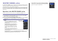
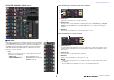


Table Of Contents
- How to Use This Reference Manual
- Contents
- Function Tree
- SELECTED CHANNEL section
- Centralogic section
- Input and output patching
- Input channels
- Signal flow for input channels
- Specifying the channel name/icon
- HA (head amp) settings
- Sending the signal from an input channel to the STEREO/MONO bus
- Added pan function (Monaural input channels only)
- Sending a signal from an input channel to a MIX/ MATRIX bus
- Channel name display indication
- Correcting delay between channels (Input Delay)
- Surround output for input channels
- Channel library operations
- OUTPUT channels
- EQ and Dynamics
- Channel Job
- Scene memory
- Monitor and Cue functions
- Talkback and Oscillator
- Meters
- Graphic EQ, Parametric EQ, Effects, and PREMIUM RACK
- I/O devices and external head amps
- MIDI
- Recorder
- AFC IMAGE Control
- Setup
- About the SETUP screen
- User settings
- Preferences
- USER DEFINED keys
- Functions that can be assigned to USER DEFINED keys
- USER DEFINED knobs
- Functions that can be assigned to USER DEFINED knobs
- Assignable encoders
- Functions that can be assigned to the assignable encoders
- GAIN/PAN/ASSIGN knob (assignable encoder) functions
- Custom fader bank
- Main fader
- Custom fader bank functions
- Console Lock
- Saving and loading setup data to and from a USB flash drive
- Formatting a USB flash drive
- Word clock and slot settings
- Using cascade connections
- Basic settings for MIX buses and MATRIX buses
- Switching the entire phantom power supply on/off
- Specifying the brightness of the touch screen, LEDs, channel name displays, and lamps
- Setting the date and time of the internal clock
- Setting the network address
- Dante audio network settings
- Dante Device Lock
- Support for Dante Domain Manager
- Using GPI (General Purpose Interface)
- Help function
- Other functions
- Initializing the unit to factory default settings
- Adjusting the detection point of the touch screen (Calibration function)
- Adjusting the faders (Calibration function)
- Fine-tuning the input and output gain (Calibration function)
- Adjusting the channel color (Calibration function)
- Adjusting the brightness of the channel name display
- Adjusting the contrast of the channel name display
- Initializing the console settings and Dante audio network settings
- Update procedure for NAME SUB CPU firmware
- Update function to Dante firmware
- Warning/Error Messages
- Index
- Data List
- EQ Library List
- DYNAMICS Library List
- Dynamics Parameters
- Effect Type List
- Effects Parameters
- Premium Rack Processor Parameters
- Parameters That Can Be Assigned to Control Changes
- NRPN Parameter Assignments
- Mixing Parameter Operation Applicability
- MIDI Data Format
- Input/Output Characteristics
- Electrical Characteristics
- Mixer Basic Parameters
- Pin Assignment
- MIDI Implementation Chart

SELECTED CHANNEL section
V5.8 Reference Manual
10
EQ parameter field
This field displays the 4-band EQ parameter settings. Press each
knob to open the HPF/EQ 1ch window.
1 Q knob
Specifies the Q for each band.
If the HIGH band filter type is set to LPF or H.SHELF (high-
shelving), or the LOW band filter type is set to L.SHELF (low-
shelving), the Q knob will not be displayed. Only the filter
type name will be displayed.
NOTE
• Fully rotating the HIGH band Q knob on the panel counter-
clockwise while pressing and holding it down will set the filter
type to LPF. Fully rotating the Q knob clockwise while pressing
and holding it down will set the filter type to high-shelving.
• Fully rotating the LOW band Q knob on the panel clockwise while
pressing and holding it down will set the filter type to low-
shelving.
• If an output channel has been selected, fully rotating the LOW
band Q knob on the panel counter-clockwise while pressing and holding it down will set the filter
type to HPF.
• You can also switch the filter type in the HPF/EQ 1ch window.
2 FREQUENCY knob
Sets the center frequency (or cutoff frequency) for each band.
3 GAIN knob
Sets the amount of cut/boost for each band.
NOTE
• If the HIGH band filter type is set to LPF, you can switch LPF on or off using the HIGH band GAIN
knob on the panel.
• If the LOW band filter type is set to HPF, you can switch HPF on or off using the LOW band GAIN
knob on the panel.
NOTE
When the BYPASS button is on, the knobs turn gray.
EQ graph field
This field graphically indicates the approximate response of the EQ. Press this field to open
the HPF/EQ 1ch window, in which you can set the attenuator, HPF, and EQ.
DYNAMICS1/DYNAMICS2 field
This field enables you to set the Dynamics 1/2 parameters.
1 OVER indicator
Warns you when the signal is clipping.
2 Level meter
Displays the output signal level (green) and the amount of gain reduction (orange)
when the Dynamics is on. The current threshold setting is shown as a white vertical line.
3 Threshold
Specifies the threshold.
4 Parameters
Indicate the values of parameters that vary depending on the currently-selected
dynamics type.
Press this field to open the DYNAMICS 1/DYNAMICS 2 1ch window, in which you can
make detailed parameter settings.
1 2 3
1 2
3
4