
User Manual

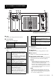
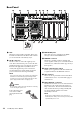
Table Of Contents

DSP-RX(-EX) Owner’s Manual
10
Rear Panel
1 Vent
This unit is equipped with cooling fans. These vents
let warm air out from the unit. Please make sure that
you do not block the vents with any object.
2 AC IN connectors
Use these sockets to connect the supplied power
cords. First connect the AC power cords to this unit,
and then insert the power cord plugs into AC outlets.
Insert the cable plug all the way until it locks in
securely. The supplied AC power cords feature a
V-lock mechanism via a latch, which prevents the
power cords from disconnecting accidentally.
NOTE
If you connect the power cords to both power supply units
A and B, both of them will supply power during normal
operation. If one of the power supply units fails, the other
power supply unit will continue to supply power.
Caution
Be sure to turn off the power to the unit before connecting
or disconnecting the power cord.
To disconnect the power
cord, remove it while
pressing the latch on the
plug.
3 MIDI OUT/IN jacks
These jacks are used to transmit/receive MIDI
messages to/from external MIDI devices.
4 REMOTE connector
This D-sub 9-pin male connector transmits and
receives signals to enable you to control the unit from
external devices. (This feature will be supported by a
future update.)
5 Serial communication switch
Enables you to toggle between RS-232C and RS-422
as signal standards for the REMOTE connector.
6 GPI connector
This is a D-sub 25-pin female connector that allows
communication (8-in, 8-out) with a GPI-equipped
external device.
7 FAULT OUTPUT connectors
This Euroblock connector is used to abnormal status
information to the outside of the unit. Connect a
lamp or buzzer here. The NC and C terminals will
short-circuit if the unit is operating normally. The
NO and C terminals will short-circuit if an
abnormality is detected.
NOTE
The NO and C terminals will also short-circuit if you
intentionally turn off the power to the unit, just as they will if
a problem with power occurs.
4 65 7 )9
&@ ^
#$ %
!
*
3 812