
User Manual


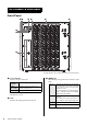
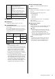

Table Of Contents

RPio622 Owner’s Manual
9
4 [U]/[D] keys
Enable you to select a setting parameter or value.
5 [ENTER] key
Confirms the setting parameter or the value.
6 [+48V MASTER] switch
This is the master switch for the unit’s +48V phantom
power supply.
If the [+48V MASTER] switch is off, no phantom
power will be supplied to the unit’s input connectors
even if phantom power to individual channels is
turned on.
NOTICE
• Make sure that the master switch for the phantom power
is turned OFF unless it is needed.
• If you plan to turn phantom power ON, first make sure
that no equipment other than phantom-powered devices
are connected to the INPUT connectors. Applying
phantom power to a device that does not require
phantom power can damage the connected device.
• Do not connect or disconnect a device to an INPUT
while phantom power is applied. Doing so can damage
the connected device and/or the unit itself.
• To prevent possible damage to speakers, make sure that
power amplifiers and/or powered speakers are turned
OFF when switching phantom power ON or OFF. We
also recommend that you set all output controls on the
control surface to minimum when turning phantom
power ON or OFF. Otherwise, sudden high level peaks
caused by the switching operation can damage
equipment as well as the hearing of those present.
7 Mini-YGDAI SLOT1/SLOT2
Enable you to install optional Mini-YGDAI I/O
cards.
8 RY card slots 1–6
Enables you to install optional RY cards to configure
I/O ports.
The unit supports the following RY cards.
(as of August 2015)
• RY16-ML-SILK
• RY16-DA
• RY16-AE
For the latest information, refer to the Yamaha Pro
Audio website.
http://www.yamahaproaudio.com/
9 [I]/[P] (Power switch)/
Power indicator
Toggles between power on (I) and off (P). When the
power unit is turned on, the indicator lights up.
Caution
• Rapidly turning the unit on and off in succession can
cause it to malfunction. After turning the unit off, wait for
at least 6 seconds before turning it on again.
• Even when the power switch is turned off, a small
amount of current is flowing through the unit. If you plan
not to use the unit for a long period of time, remove the
power cord from the AC outlet.
NOTE
To maintain power supply redundancy, turn both power
supply units A and B ON or OFF together. If only one
power supply unit is ON, the LCD will display an error
message and the color indicator will light up yellow.
FaultOut Specifies the conditions under which an
alert for abnormality is transmitted from the
FAULT OUTPUT connector.
Red: An alert is transmitted if an error
occurs that causes the color indicator to
flash red.
Y&R: An alert is transmitted if an error
occurs that causes the color indicator to
light up yellow steadily or flash red.
F/W Ver. Indicates the current firmware version
number of the unit.
Initialz Initializes the unit.
[+48V MASTER]
switch
Channel
phantom power
Channel +48V
indicator
On
On
Light up
steadily
Off Flash
On
Off Dark
Off