I/O RACK RPio622 Bedienungsanleitung AUDIO INTERFACE DE
The above warning is located on the rear of the unit. L’avertissement ci-dessus est situé sur l’arrière de l’unité. Explanation of Graphical Symbols Explication des symboles The lightning flash with arrowhead symbol within an equilateral triangle is intended to alert the user to the presence of uninsulated “dangerous voltage” within the product’s enclosure that may be of sufficient magnitude to constitute a risk of electric shock to persons.
PA_de_6 1/2 VORSICHTSMASSNAHMEN BITTE SORGFÄLTIG DURCHLESEN, EHE SIE FORTFAHREN Bitte heben Sie dieses Handbuch sorgfältig auf, damit Sie später einmal nachschlagen können. WARNUNG Beachten Sie stets die nachfolgend beschriebenen Vorsichtsmaßnahmen, um mögliche schwere Verletzungen oder sogar tödliche Unfälle infolge eines elektrischen Schlags, von Kurzschlüssen, Feuer oder anderen Gefahren zu vermeiden.
PA_de_6 2/2 ACHTUNG Aufstellort • Stellen Sie das Gerät nicht an einer instabilen Position ab, wo es versehentlich umstürzen und Verletzungen verursachen könnte. • Blockieren Sie nicht die Lüftungsöffnungen. Das Gerät hat Lüftungsschlitze an der Vorder-/Rückseite, um eine Überhitzung zu vermeiden. Legen Sie dasGerät insbesondere nicht auf die Seite oder auf den Kopf. Unzureichende Belüftung kann zu Überhitzung führen und u. U. das Gerät beschädigen oder sogar einen Brand auslösen.
Inhalt Einleitung.................................................................6 Die wichtigsten Leistungsmerkmale .....................................6 Zubehör............................................................................... 6 Firmware-Updates................................................................6 Vorsichtsmaßnahmen für die Rack-Montage ........................6 Versenkter Einbau ................................................................
Einleitung Vielen Dank für den Kauf des I/O-Racks RPio622 von Yamaha. Das RPio622 ist ein Audio Interface, mit dem Sie die Ein-/Ausgänge für das RIVAGE-PM10-System flexibel konfigurieren können, wie es Ihre Anwendung und Systemgröße erfordert. Damit Sie die herausragende Funktionalität des RPio622 voll nutzen und das Gerät über Jahre hinweg ohne Probleme einsetzen können, lesen Sie bitte diese Anleitung, bevor Sie beginnen, das Produkt einzusetzen.
Bezeichnungen und Funktionen der Teile Vorderseite 12 3 4 8 9 5 6 7 Diese Abbildung zeigt ein Rack, bei dem bereits RY-Karten installiert wurden. 1 Farbanzeige Zeigt den Status der Einheit an. Rot (blinkt) Ein schwerer Fehler ist aufgetreten. Gelb (leuchtet stetig) Zeigt ein kleineres Problem an, Sie können den Betrieb der Einheit fortsetzen. Grün Normal 3 [MENU]-Taste Die beiden folgenden Parametereinstellungen werden im LC-Display angezeigt: Unit ID Gibt die Unit ID der Einheit an.
FaultOut Gibt die Bedingungen an, unter denen am Anschluss FAULT OUTPUT ein Alarm für ungewöhnliche Betriebsbedingungen ausgegeben wird. Red: Es wird ein Alarm ausgegeben, wenn ein Fehler auftritt, der dazu führt, dass die Farbanzeige rot blinkt. Y&R: Es wird ein Alarm ausgegeben, wenn ein Fehler auftritt, der dazu führt, dass die Farbanzeige stetig gelb leuchtet oder rot blinkt. F/W Ver. Gibt die aktuelle Versionsnummer der Firmware der Einheit ein. Initialz Initialisiert die Einheit.
Rückseite ! @ # ) $ % ^ ) Anschlüsse AC IN An diesen Buchsen werden die mitgelieferten Netzkabel angeschlossen. Schließen Sie zuerst die Netzkabel an dieser Einheit an, und stecken Sie dann die Netzstecker in zwei Netzsteckdosen. Schieben Sie die Kabelstecker vollständig hinein, bis sie sicher einrasten. Die mitgelieferten Netzkabel besitzen einen speziellen Verriegelungsmechanismus (VLock), der verhindert, dass die Netzkabel versehentlich herausgezogen werden.
@ Anschlüsse FAULT OUTPUT Dieser Euroblock-Anschluss dient der Übermittlung ungewöhnlicher Statusinformationen an einen entfernten Ort. Schließen Sie hier eine Leuchte oder einen Summer an. Der Anschluss C ist mit dem Anschluss NC durchverbunden, so lange sich das Gerät normal verhält. Die Anschlüsse NO und C sind miteinander verbunden, wenn ein ungewöhnlicher Zustand eintritt.
Einbauen eines Euroblock-Steckers 2. Führen Sie die Kabelenden ein. Für die Verbindung mit dem FAULT-OUTPUT-Anschluss müssen Sie den mitgelieferten Euroblock-Stecker verwenden. NO C NC Vorbereitung (der Kabel) Ca. 7 mm Ca. 20 mm • Verwenden Sie Litzendraht für den EuroblockStecker. Entfernen Sie zuerst die Isolierung von der Litze, wie unten gezeigt.
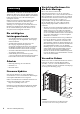
Einbau und Ausbau optionaler Karten 3. Richten Sie die Kanten der Karte auf die Führungsschienen im Slot aus, und setzen Sie dann die Karte in den Slot ein. Drücken Sie die Karte ganz in den Slot hinein, so dass der Stecker am Ende der Karte sicher im Anschluss innerhalb des Slots steckt. Einbau einer RY-Karte 1. Vergewissern Sie sich, dass keine der beiden Netzanzeigen leuchten. Vorsicht Ein- oder Ausbau einer Karte bei eingeschaltetem Gerät kann zu Ausfall oder elektrischem Schlag führen. 2.
Ausbau der RY-Karte 1. 3. Vergewissern Sie sich, dass keine der beiden Netzanzeigen leuchten. Vorsicht Ein- oder Ausbau einer Karte bei eingeschaltetem Gerät kann zu Ausfall oder elektrischem Schlag führen. 2. Lösen Sie die Schrauben, mit denen die Karte gehalten wird. 3. Ziehen Sie die Karte zu sich, während Sie sie an den Schrauben festhalten. 4. Setzen Sie die aufbewahrte Abdeckung wieder auf und befestigen Sie sie mit den Schrauben.
Einbau einer HY-Karte 1. 4. Vergewissern Sie sich, dass keine der beiden Netzanzeigen leuchten. Vorsicht Ein- oder Ausbau einer Karte bei eingeschaltetem Gerät kann zu Ausfall oder elektrischem Schlag führen. 2. Ziehen Sie den Installationshebel nach oben, um die Karte zu verriegeln. Achten Sie darauf, dass die Krallen des Hebels genau in die Öffnungen unter der Vorderkante der Karte greifen.
Netzteil Anschließen des Netzkabels 1. Schalten Sie beide Netzschalter A und B des Geräts ein. 2. Schließen Sie eines der beiliegenden Netzkabel am Anschluss AC IN (A) an, und das andere am Anschluss AC IN (B). 3. Schließen Sie das jeweils andere Ende der Netzkabels an zwei Netzsteckdosen verschiedener Sicherungskreise an. HINWEIS • Um die Netzkabel zu trennen, entfernen Sie die Kabel in der Reihenfolge Schritt 1➝3➝2 des oben angegebenen Vorgangs.
Liste der Meldungen Eine Fehlermeldung für Vorsicht oder Achtung wird im vorderen LC-Display angezeigt und gleichzeitig an der Farbanzeige dargestellt. Fehlermeldungen, die zur Vorsicht ermahnen Es könnte eine Reparatur notwendig sein. Wenden Sie sich an Ihren Yamaha-Händler. LCD-Events Status der Farbanzeige Beschreibung M1 [ERR R0*] H/W ERROR RY SLOT* Rot (blinkt) Eine in den RY-Kartenschacht eingesetzte Karte ist nicht verfügbar.
Technische Daten Allgemeine Technische Daten Sampling-Frequenz Bedingungen Externe Clock Interne Clock Frequenzbereich Fs= 44,1 kHz, 48 kHz, 88,2 kHz, 96 kHz Jitter des PLL*1 WORD CLOCK IN Fs = 44,1 kHz, 48 kHz, 88,2 kHz, 96 kHz Frequenz Wordclock: int 44,1 kHz Wordclock: int 48 kHz Wordclock: int 88.2 kHz Wordclock: int 96 kHz Genauigkeit *2 Wordclock: int 44,1 kHz Wordclock: int 48 kHz Wordclock: int 88,2 kHz Wordclock: int 96 kHz Jitter *1. *2.
Abmessungen (BxHxT), Gewicht 480 mm x 455 mm x 490 mm (einschließlich Gummifüßen), 29 kg Zubehör Bedienungsanleitung (dieses Dokument), Netzkabel (x 2), Euroblock-Stecker (dreipolig) Optionales Zubehör RY-Karte, HY-Karte, Mini-YGDAI-Karte Größe für EIA-Rack-Montage 10 HE Verbraucherinformation zur Sammlung und Entsorgung alter Elektrogeräte Befindet sich dieses Symbol auf den Produkten, der Verpackung und/oder beiliegenden Unterlagen, so sollten benutzte elektrische Geräte nicht mit dem normalen Haushal
Abmessungen 490 13 450 350 65 15 440 455 480 50 350 Einheit: mm Annähernder Munsell-Wert der Außenfarbe: N5 RPio622 – Bedienungsanleitung 19
Software-Lizenzen und Urheberrechte Dieses Produkt enthält die folgende Software von Drittherstellern. Für Informationen (Urhebrrecht usw.) über die jeweilige Software lesen Sie bitte die unten angegebenen Geschäftsbedingungen. Durch Verwendung dieses Produkts wird angenommen, dass Sie die Geschäftsbedingungen akzeptiert haben. expat Copyright (c) 1998, 1999, 2000 Thai Open Source Software Center Ltd and Clark Cooper Copyright (c) 2001, 2002, 2003 Expat maintainers.
Index A K Anschließen des Netzkabels...........................15 Karte Ausbau HY-Karte.............................................. 14 MY-Karte ............................................. 13 RY-Karte .............................................. 13 Einbau HY-Karte.............................................. 14 MY-Karte ............................................. 13 RY-Karte .............................................. 12 Einbau/Ausbau..........................................
For details of products, please contact your nearest Yamaha representative or the authorized distributor listed below. Pour plus de détails sur les produits, veuillez-vous adresser à Yamaha ou au distributeur le plus proche de vous figurant dans la liste suivante. NORTH AMERICA CANADA Yamaha Canada Music Ltd. 135 Milner Avenue, Toronto, Ontario, M1S 3R1, Canada Tel: +1-416-298-1311 U.S.A. Yamaha Corporation of America 6600 Orangethorpe Avenue, Buena Park, CA 90620, U.S.A.
Yamaha Pro Audio global website: http://www.yamahaproaudio.com/ Yamaha Downloads http://download.yamaha.