
user manual

2-3
2
Connection
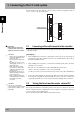
3. Setting the CC-Link compatible module
To connect the CC-Link system specification controller to the CC-Link system, the station No. and
communication speed must be set with the rotary switch on the CC-Link compatible module. Confirm
the curr ent station No. and communication speed with the procedures given in s ection 1.
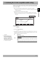
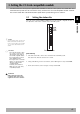
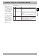
3.1 Setting the station No.
Using the rotary switches MSB and LSB in front of the CC-Link compatible module, set
the station No. of the robot controller in the CC-Link system.
1
2
3
4
5
6
7
8
9
0
1
2
3
4
5
6
7
8
9
0
1
2
3
4
5
6
7
8
9
0
MSB
LSB
Front of the unit
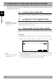
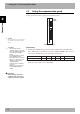
[Procedures]
1. Check the station No. of the robot controller in the CC-Link system.
The station No. must be set between 1 and 61.
2. Using a flat-blade precision screwdriver, set the 10th digit on rotary switch MSB.
3. In the same manner, set the 1st digit on rotary switch LSB.
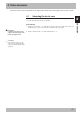
n
NOTE
Up to 64 stations can be set in the CC-
Link system, but the CC-Link system
itself occupies 4 stations (specified No.
+3), so set the station No. between 1
and 61.
c
CAUTION
• Never directly touch the conduc-
tive sections or electronic parts
other than the rotary switch on
the CC-Link compatible module.
• Do not apply impact on the CC-
Link compatible module.
• Do not place water or conductive
matters, etc., which could cause
damage near the CC-Link
compatible module.
• Accurately set the station No.
• Make sure not to set the rotary
switch BPS by mistake.
w
WARNING
When setting the station No.,
completely shut off the power
supplied to the robot controller.