AV Receiver Owner’s Manual Read the supplied booklet “Safety Brochure” before using the unit.
CONTENTS Accessories . . . . . . . . . . . . . . . . . . . . . . . . . . . . . . . . . . . . . . . . . . . . . . . . . . . . . . 5 FEATURES 6 8 Selecting an on-screen menu language . . . . . . . . . . . . . . . . . . . . . . . . . 49 9 Optimizing the speaker settings automatically (YPAO) . . . . . . . . . . 50 Measuring at one listening position (single measure) . . . . . . . . . . . . . . . . . . . . . . . . . . . . . . . . . . . . . . . . . . . . . . .
Playing back music stored on a USB storage device . . . . . . . . . . . . . . . 81 Network . . . . . . . . . . . . . . . . . . . . . . . . . . . . . . . . . . . . . . . . . . . . . . . . . . . . . . . . . . . . . . . . . . . . . . . . . . . . . . . . . . . . . . . . .125 Connecting a USB storage device . . . . . . . . . . . . . . . . . . . . . . . . . . . . . . . . . . . . . . . . . . . . . . . . . . . . . . . . . . . . . . . . . . 81 Multi Zone . . . . . . . . . . . . . . . . . . . . . . . . . . . . . .
Error indications on the front display . . . . . . . . . . . . . . . . . . . . . . . . . . . . 155 Glossary . . . . . . . . . . . . . . . . . . . . . . . . . . . . . . . . . . . . . . . . . . . . . . . . . . . . . . . 156 Audio information . . . . . . . . . . . . . . . . . . . . . . . . . . . . . . . . . . . . . . . . . . . . . . . . . . . . . . . . . . . . . . . . . . . . . . . . . . . . . . . 156 HDMI and video information . . . . . . . . . . . . . . . . . . . . . . . . . . . . . . . . . . . . . . . . . .
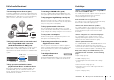
Accessories Operating range of the remote control Check that the following accessories are supplied with the product. • Point the remote control at the remote control sensor on the unit and remain within the operating range shown below. Remote control Batteries (x4) Within 6 m (20 ft) 30° *RX-A3030: AAA, LR03, UM-4 RX-A2030: AAA, R03, UM-4 AM antenna 30° Insert the batteries the right way round. FM antenna *One of the above is supplied depending on the region of purchase.
FEATURES What you can do with the unit Wide variety of supported content • iPod/iPhone/iPad . p.77 • USB . p.81 • Media server (PC/NAS) . p.84 • Internet radio . p.87 • AirPlay . p.89 Supports 2- to 9-channel (plus rear presence) speaker system and up to 2 subwoofer connections. Allows you to enjoy favorite acoustic spaces in various styles. • Automatically optimizing the speaker . p.50 settings to suit your room (YPAO) • Reproducing stereo or multichannel . p.
Full of useful functions! Useful tips ❑ Connecting various devices (p.41) ❑ Listening to FM/AM radio (p.70) A number of HDMI jacks and various input/output jacks on the unit allow you to connect video devices (such as BD/DVD players), audio devices (such as CD players), game consoles, camcorders, and other devices. The unit is equipped with a built-in FM/AM tuner. You can register up to 40 favorite radio stations as presets.
CINEMA DSP The excitement of a concert hall and the powerful sense of being inside a movie - we all want to enjoy these experiences in our own living room. Yamaha has pursued the fulfillment of these desires for more than 20 years, and this fulfillment has now taken shape as the Yamaha AV receivers.
Unrivaled audio and video quality High-resolution music enhancer Hi-bit high-sampling extension up to 96 kHz / 24-bit can be applied to lossless 44.1/48 kHz content such as from a CD (2-channel PCM) or a FLAC file for further heightening of the musicality in the original content (p.102) Loudness Before processing Playback bandwidth of a 44.
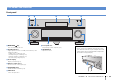
Part names and functions Front panel 1 2 3 4 5 MAIN ZONE PURE DIRECT VOLUME INPUT ON SCREEN OPTION SCENE TONE/BALANCE STRAIGHT 1 2 ZONE 2 ZONE 3 3 MULTI ZONE PROGRAM INFO MEMORY PRESET FM AM TUNING 4 ENTER RETURN ZONE 4 ZONE CONTROL DISPLAY VIDEO AUX PHONES YPAO MIC SILENT CINEMA 5V 6 1 MAIN ZONE z key Turns on/off (standby) the unit. 2 Standby indicator Lights up when the unit is in standby mode under any of the following conditions. • HDMI Control is enabled (p.
■ Inside of the front panel door 9 0 AB C ON SCREEN OPTION DE F GH SCENE TONE/BALANCE STRAIGHT 1 2 3 K INFO MEMORY PRESET FM AM TUNING L 4 MULTI ZONE PROGRAM IJ ENTER ZONE 2 RETURN ZONE 3 ZONE 4 ZONE CONTROL DISPLAY VIDEO AUX PHONES YPAO MIC SILENT CINEMA 5V 2.1A M 9 ON SCREEN key Displays the on-screen menu on the TV. 0 Menu operations keys Cursor keys Select a menu or a parameter. ENTER Confirms a selected item. RETURN Returns to the previous screen.
Front display (indicators) 1 2 3 5 4 6 HD STEREO TUNED PARTY ZONE ZONE ZONE 3 4 IN OUT 1 OUT 2 2 ENHANCER SLEEP HD 9 0 PL L C R PR SL SW1 SW2 SR PL SBL SB SBR PR A B Lights up when HDMI signals are being input or output. IN Lights up when HDMI signals are being input. OUT1/OUT2 Indicates the HDMI OUT jacks currently outputting an HDMI signal. 2 STEREO Lights up when the unit is receiving a stereo FM radio signal. TUNED Lights up when the unit is receiving an FM/AM radio station signal.
Rear panel 1 2 3 456 7 89 0 A B C D E (RX-A3030 U.S.A. model) DC OUT 5V 0.5A NETWORK HDMI OUT ( 3 NET ) 1 2 ARC PHONO AV 1 AV 2 AV 3 AV 4 (1 BD/DVD) HDMI (ZONE OUT) MONITOR OUT/ ZONE OUT AV OUT Y AV 1 AV 2 AV 3 RS-232C AV 4 AV 5 AV 6 AV 7 (1 BD/DVD) PB COMPONENT VIDEO PR Y AV 3 PB TRIGGER OUT PR C AV 1 A Y GND MONITOR OUT/ZONE OUT PB PR 1 REMOTE 1 IN OUT PRE OUT (SINGLE) (FRONT) SURROUND SUR.
(RX-A3030 U.S.A. model) DC OUT 5V 0.5A NETWORK 1 2 ARC PHONO AV 1 AV 2 AV 3 AV 4 (1 BD/DVD) HDMI HDMI OUT ( 3 NET ) (ZONE OUT) MONITOR OUT/ ZONE OUT AV OUT Y AV 1 AV 2 AV 3 RS-232C AV 4 AV 5 AV 6 AV 7 (1 BD/DVD) PB COMPONENT VIDEO PR Y AV 3 PB TRIGGER OUT PR C AV 1 A Y GND MONITOR OUT/ZONE OUT PB PR 1 REMOTE 1 IN OUT PRE OUT (SINGLE) (FRONT) SURROUND SUR.
Remote control 1 Remote control signal transmitter 1 Transmits infrared signals. 2 2 SOURCE z key SOURCE RECEIVER Turns on/off an external device. SOURCE/RECEIVER key 3 Changes the device (the unit or external device) that is operated with the remote control (p.140). You can operate the unit when this key lights up in orange, and an external device when this key lights up in green.
■ Inside of the remote control cover I Sound mode keys Select a sound mode (p.64). SOURCE RECEIVER J INFO key Selects the information displayed on the front display (p.98). K Numeric keys AV 1 2 3 4 5 6 7 V-AUX 1 2 3 4 PHONO MULTI USB NET TUNER [A] [B] [C] Let you enter numerical values, such as radio frequencies. L ZONE key Changes the zone that is controlled by the remote control (p.96). AUDIO M PARTY key Turns on/off the party mode (p.97).
PREPARATIONS General setup procedure 1 Connecting speakers (p.18) Basic speaker configuration (p.19) Select the speaker layout and connect the speakers to the unit. Advanced speaker configuration (p.24) Apply bi-amp connections, channel expansion (using an external power amplifier) or multi-zone configurations to enhance the system. 2 Connecting a TV (p.35) Connect a TV to the unit. 3 Connecting playback devices (p.
1 Speaker connections 2 3 4 5 6 7 8 9 1 Connecting speakers The unit has 9 built-in amplifiers. You can connect 2 to 11 speakers and up to 2 subwoofers to create the favorite acoustic space in your room. You can also apply bi-amp connections, channel expansion (using an external power amplifier) or multi-zone configurations to enhance your system (p.24). Caution • Under its default settings, the unit is configured for 8-ohm speakers.
1 Speaker connections 2 3 4 5 6 7 8 9 Basic speaker configuration ■ Placing speakers in your room Depending on the number of speakers, place the speakers and subwoofer in your room. This section describes the representative speaker layout examples. ❑ 9.2+2-channel system (using both surround back and rear presence speakers) E R 1 9 E 2 3 R 1 9 4 9 5 T Y 6 ❑ 9.
1 Speaker connections 2 3 4 5 6 7 8 9 ❑ 9.2-channel system (using surround back speakers) E ❑ 7.1-channel system (using surround back speakers) R 1 9 2 3 9 4 5 6 7 This speaker system uses the front presence speakers to produce a natural 3-dimensional sound field, and also allows you to enjoy extended surround sounds using the surround back speakers.
1 Speaker connections 2 3 4 5 6 7 8 9 ❑ Front 5.1-channel system ■ Setting the speaker impedance Under its default settings, the unit is configured for 8-ohm speakers. When connecting 6-ohm speakers, set the speaker impedance to “6 MIN”. In this case, you can also use 4-ohm speakers as the front speakers. 1 Before connecting speakers, connect the power cable to an AC wall outlet. 2 While holding down STRAIGHT on the front panel, press MAIN ZONE z.
1 Speaker connections 2 3 4 5 6 7 8 9 ■ Connecting speakers Cables necessary for connection (commercially available) Speaker cables (x the number of speakers) Connect the speakers placed in your room to the unit. + – Caution • Remove the unit’s power cable from an AC wall outlet and turn off the subwoofer before connecting the speakers. • Ensure that the core wires of the speaker cable do not touch one another or come into contact with the unit’s metal parts.
1 Speaker connections 2 3 4 5 6 7 8 9 ❑ Connecting speaker cables Speaker cables have two wires. One is for connecting the negative (-) terminal of the unit and the speaker, and the other is for the positive (+) terminal. If the wires are colored to prevent confusion, connect the black wire to the negative and the other wire to the positive terminal. a Remove approximately 10 mm (3/8”) of insulation from the ends of the speaker cable, and twist the bare wires of the cable firmly together.
1 Speaker connections 2 3 4 5 6 7 8 9 Advanced speaker configuration In addition to the basic speaker configuration (p.19), the unit also allows you to apply the following speaker configurations to enhance your system. Using the four internal amplifiers for front speakers to have more high-quality sounds Bi-amp connection Combining with an external power amplifier (Hi-Fi amplifier, etc.
1 Speaker connections 2 3 4 5 6 7 8 9 ■ Available speaker configurations (RX-A3030) Main zone Speaker configuration Output channel (max) Bi-amp Using a bi-amp connection in the main zone 7 Using a bi-amp connection in the main zone and multi-zone speakers 7 Using a bi-amp connection in the main zone and power-amp channel expansion (for presence channels) Using power-amp channel expansion (for front and/or presence channels) Using power-amp channel expansion (for front channels) and multi-zon
1 Speaker connections 2 3 4 5 6 7 8 9 ❑ 7ch BI-AMP ❑ 7ch BI-AMP +1ZONE Bi-amp 1 9 Bi-amp 1 2 3 9 9 4 5 2 2 9 3 4 5 6 6 1 7 7 Zone3 Main zone Speaker Connect to Speaker Connect to 12 FRONT and EXTRA SP 1 (bi-amp connection) 12 FRONT and EXTRA SP 1 (bi-amp connection) 3 CENTER 3 CENTER 45 SURROUND 45 SURROUND 67 SURROUND BACK 67 SURROUND BACK ER (not used) ER (not used) TY (not used) TY (not used) 9 SUBWOOFER 1–2 9 SUBWOOFER 1–2 Zone3 speakers EXTRA SP 2
1 Speaker connections 2 3 4 5 6 7 8 9 ❑ 7ch BI-AMP +FP+RP (RX-A3030 only) ❑ 9ch +RP (RX-A3030 only) Bi-amp E R 1 R 2 3 9 1 9 4 Speaker 7 9 4 Y 6 2 3 9 5 T via external amp E via external amp via external amp 5 T via external amp via external amp Connect to Y 6 Speaker 7 Connect to 12 FRONT and EXTRA SP 1 (bi-amp connection) 12 FRONT 3 CENTER 3 CENTER 45 SURROUND 45 SURROUND 67 SURROUND BACK 67 SURROUND BACK ER F.
1 Speaker connections 2 3 4 5 6 7 8 9 ❑ 9ch +FRONT (RX-A3030 only) ❑ 7ch +FP+RP (RX-A3030 only) via external amp E R E R via external amp via external amp 1 2 3 9 1 9 4 T Speaker 7 9 4 Y 6 3 9 5 2 5 T via external amp Connect to Y 6 Speaker 7 Connect to 12 FRONT (PRE OUT) via external power amplifier 12 FRONT 3 CENTER 3 CENTER 45 SURROUND 45 SURROUND 67 SURROUND BACK 67 SURROUND BACK ER EXTRA SP 1 ER F.
1 Speaker connections 2 3 4 5 6 7 8 9 ❑ 7ch +FRONT+1ZONE ❑ 5ch +FRONT+2ZONE via external amp via external amp E R 1 9 2 1 1 2 9 3 4 9 5 6 1 2 9 3 4 7 5 6 2 Zone2 7 1 Zone3 2 Main zone Main zone Zone3 Speaker Connect to Speaker Connect to 12 FRONT (PRE OUT) via external power amplifier 12 FRONT (PRE OUT) via external power amplifier 3 CENTER 3 CENTER 45 SURROUND 45 SURROUND 67 SURROUND BACK 67 SURROUND BACK ER EXTRA SP 1 ER (not used) TY (not used) TY
1 Speaker connections 2 3 4 5 6 7 8 9 ❑ 7ch +1ZONE ❑ 9ch +1ZONE E 1 9 2 1 4 9 2 1 5 6 7 7 Zone3 Zone2 Main zone Speaker 2 9 3 4 5 6 1 2 9 3 R Main zone Connect to Speaker Connect to 12 FRONT 12 FRONT 3 CENTER 3 CENTER 45 SURROUND 45 SURROUND 67 SURROUND BACK 67 SURROUND BACK ER (not used) ER EXTRA SP 1 TY (not used) TY (not used) 9 SUBWOOFER 1–2 9 SUBWOOFER 1–2 Zone2 speakers EXTRA SP 1 Zone3 speakers EXTRA SP 2 • When Zone3 output is enabled (p.
1 Speaker connections 2 3 4 5 6 7 8 9 ❑ 7ch +2ZONE 1 9 1 2 9 3 4 5 6 2 Zone2 7 1 2 Main zone Zone3 Speaker Connect to 12 FRONT 3 CENTER 45 SURROUND 67 SURROUND BACK ER (not used) TY (not used) 9 SUBWOOFER 1–2 Zone2 speakers EXTRA SP 1 Zone3 speakers EXTRA SP 2 • When Zone3 output is enabled (p.96), the surround back speakers in the main zone do not output sound.
1 Speaker connections 2 3 4 5 6 7 8 9 ■ Connecting front speakers that support bi-amp connections ■ Connecting Zone2/3 speakers When using front speakers that support bi-amp connections, connect them to the FRONT terminals and EXTRA SP 1 terminals. When using Zone2/3 speakers, connect them to the EXTRA SP 1–2 terminals. To enable the bi-amp function, configure the “Power Amp Assign” setting (p.116) in the “Setup” menu after connecting the power cable to an AC wall outlet.
1 Speaker connections 2 3 4 5 6 7 8 9 ■ Connecting an external power amplifier When connecting an external power amplifier (pre-main amplifier) to enhance speaker output, connect the input jacks of the power amplifier to the PRE OUT jacks of the unit. The same channel signals are output from the PRE OUT jacks as from their corresponding SPEAKERS terminals.
Input/output jacks and cables ■ Video/audio jacks ■ Video jacks ■ Audio jacks ❑ HDMI jacks ❑ COMPONENT VIDEO jacks ❑ OPTICAL jacks Transmit digital video and digital sound through a single jack. Use an HDMI cable. Transmit video signals separated into three components: luminance (Y), chrominance blue (PB), and chrominance red (PR). Use a component video cable with three plugs. Transmit digital audio signals. Use a digital optical cable. Remove the tip protector (if available) before using the cable.
1 2 TV connection 3 4 5 6 7 8 9 2 Connecting a TV Connect a TV to the unit so that video input to the unit can be output to the TV. You can also enjoy playback of TV audio on the unit. ■ Connection Method 1 (HDMI Control/ARC-compatible TV) Connect the TV to the unit with an HDMI cable. The connection method varies depending on the functions and video input jacks available on your TV. Refer to the instruction manual of the TV and choose a connection method.
1 2 TV connection 3 4 5 6 7 8 9 ❑ Necessary settings To use HDMI Control and ARC, you need to configure the following settings. 3 Configure the settings for HDMI Control. For details on settings and operating your TV, refer to the instruction manual for the TV. a Enable HDMI Control on the TV and playback devices (such as HDMI Control-compatible BD/DVD player).
1 2 TV connection 3 4 5 6 7 8 9 ■ Connection Method 2 (HDMI Control-compatible TV) ❑ Necessary settings Connect the TV to the unit with an HDMI cable and an audio cable (digital optical or stereo pin cable). To use HDMI Control, you need to configure the following settings. • The following explanation is based on the assumption that you have not changed the “HDMI” parameters (p.124) in the “Setup” menu. For details on settings and operating your TV, refer to the instruction manual for the TV.
1 2 TV connection 3 4 5 6 7 8 9 3 Configure the settings for HDMI Control. a Enable HDMI Control on the TV and playback devices (such as a HDMI Control-compatible BD/DVD player). ■ Connection Method 3 (TV with HDMI input jacks) Connect the TV to the unit with an HDMI cable and an audio cable (digital optical or stereo pin cable). HDMI OUT 1 jack b Turn off the TV’s main power and then turn off the unit and playback devices. c Turn on the unit and playback devices and then turn on the TV.
1 2 TV connection 3 4 5 6 7 8 9 ■ Connection Method 4 (TV without HDMI input jacks) ❑ S VIDEO connection (with an S-video cable) Depending on the video input jacks available on your TV, choose one of the following connections. If you select “AUDIO 1” as the input source by pressing AUDIO 1 or SCENE(TV) on the remote control, the TV audio will be played back on the unit. MONITOR OUT/ ZONE OUT MONITOR OUT (S VIDEO) jack The unit (rear) S DC OUT 5V 0.
1 2 TV connection 3 4 5 6 7 8 9 ■ Connecting another TV or a projector The unit has two HDMI output jacks. If you connect another TV or a projector to the unit with an HDMI cable, you can switch the TV (or projector) to be used for watching videos with the remote control (p.61). HDMI OUT 2 jack HDMI OUT The unit (rear) 1 2 ARC TV (ZONE OUT) HDMI DC OUT 5V 0.
1 2 3 Playback device connections 4 5 6 7 8 9 3 Connecting playback devices The unit is equipped with a variety of input jacks including HDMI input jacks to allow you to connect different types of playback devices. For information on how to connect an iPod or a USB storage device, see the following pages. • Connecting an iPod (p.77) ■ Component video connection Connect a video device to the unit with a component video cable and an audio cable (digital coaxial, digital optical or stereo pin cable).
1 2 3 Playback device connections 4 5 6 7 8 9 ■ S-video connection ■ Composite video connection Connect a video device to the unit with an S-video cable and an audio cable (digital coaxial, digital optical or stereo pin cable). Choose a set of input jacks (on the unit) depending on the audio output jacks available on your video device. Connect a video device to the unit with a video pin cable and an audio cable (digital coaxial, digital optical, or stereo pin cable).
1 2 3 Playback device connections 4 5 6 7 8 9 Connecting audio devices (such as CD players) PHONO jacks PHONO Connect audio devices such as CD players, MD players, and a turntable to the unit. Depending on the audio output jacks available on your audio device, choose one of the following connections. Audio output (PHONO) Ground lead GND GND The unit (rear) PHONO L L • The following explanation is based on the assumption that you have not changed the “Input Assignment” setting (p.
1 2 3 Playback device connections 4 5 6 7 8 9 Connecting to the jacks on the front panel Use the VIDEO AUX jack to temporarily connect a playback device to the unit. Use the USB jack to connect an iPod or a USB storage device. For details, see “Connecting an iPod” (p.77) or “Connecting a USB storage device” (p.81). Before making a connection, stop playback on the device and turn down the volume on the unit.
1 2 3 Playback device connections 4 FM/AM antenna connections 5 6 7 8 9 ❑ Composite video/analog stereo/digital optical connection Connect a playback device (such as game consoles and camcorders) to the unit with a video pin cable and an audio cable (digital optical or stereo pin cable). ZONE 2 ZONE 3 ZONE 4 Connect the supplied FM/AM antennas to the unit. Fix the end of the FM antenna to a wall, and place the AM antenna on a flat surface.
1 2 3 4 FM/AM antenna connections 5 Network connections 6 7 8 9 Assembling the AM antenna 5 Connecting to a network Connect the unit to your router with a commercially-available STP network cable (CAT-5 or higher straight cable). You can enjoy Internet radio or music files stored on media servers, such as PCs and Network Attached Storage (NAS), on the unit.
1 2 3 4 5 6 Other connections 7 8 9 6 Connecting other devices Connecting recording devices Connecting a device with analog multi-channel output You can connect video/audio recording devices to the AV OUT jacks. These jacks output video/audio signals selected as the input. You can connect an analog multi-channel output device such as a DVD player and an SACD player to the MULTI CH INPUT jacks.
1 2 3 4 5 6 Other connections 7 Power cable connection 8 9 Connecting a device compatible with the trigger function 7 Connecting the power cable The trigger function can control an external device in conjunction with operating the unit (such as powering on/off and input selection). If you have a Yamaha subwoofer that supports a system connection or a device with a trigger input jack, you can use the trigger function by connecting the external device to one of the TRIGGER OUT jacks.
1 2 3 4 5 6 7 8 Language setting 9 SOURCE RECEIVER RECEIVER z Select the desired on-screen menu language from English, Japanese, French, German, Spanish, Russian, Italian and Chinese. AV 1 2 3 4 5 6 7 V-AUX AUDIO 1 2 3 4 PHONO MULTI L USB NET TUNER [A] [B] [C] 8 Selecting an on-screen menu language 1 2 Press RECEIVER z to turn on the unit. 3 4 Press ON SCREEN. 5 Use the cursor keys (e/r) to select “Language” and the cursor keys (q/w) to select the desired language.
1 2 3 4 5 6 7 8 9 Automatic speaker setup SOURCE RECEIVER RECEIVER z AV 1 2 3 4 5 6 7 V-AUX AUDIO 1 2 3 4 PHONO MULTI L USB NET TUNER [A] [B] [C] 1 2 9 Optimizing the speaker settings automatically (YPAO) The Yamaha Parametric room Acoustic Optimizer (YPAO) function detects speaker connections, measures the distances from them to your listening position(s), and then automatically optimizes the speaker settings, such as volume balance and acoustic parameters, to suit your room.
1 2 3 4 5 6 7 8 9 Automatic speaker setup ❑ Multi Position The following screen appears on the TV. SOURCE RECEIVER SOURCE/RECEIVER Selects multi measure or single measure. AV 1 2 3 4 5 6 7 V-AUX AUDIO 1 2 3 4 PHONO MULTI L USB NET TUNER [A] [B] [C] SCENE 1 2 3 PROGRAM MUTE TOP MENU 4 VOLUME OPTION ON SCREEN Cursor keys ENTER ENTER RETURN DISPLAY Settings • To cancel the operation, disconnect the YPAO microphone before starting the measurement.
1 2 3 4 5 6 7 8 9 Automatic speaker setup Single measure Multi measure (5 listening positions) ❑ Angle (RX-A3030 only) Enables/disables the angle measurement. a d e bac Settings Multi measure Multi measure (1 listening position + front/back/left/right) (2 listening positions + front/back) Yes Enables the angle measurement. The unit will measure angle of each speaker at the listening position and correct the speaker parameters so that CINEMA DSP can create more effective sound fields.
1 2 3 4 5 6 7 8 9 Automatic speaker setup Measuring at one listening position (single measure) SOURCE RECEIVER 2 3 4 5 6 7 V-AUX Proceed to Step 2. When “Multi Position” is set to “No”, follow the procedure below for measurement. AV 1 (RX-A3030 [when angle measurement is enabled]) AUDIO 1 2 3 4 PHONO MULTI L USB NET TUNER [A] [B] [C] • Do not stand between the speakers and the YPAO microphone during the measurement process (about 5 minutes).
1 2 3 4 5 6 7 8 9 Automatic speaker setup c Press ENTER to start the first angle measurement. SOURCE RECEIVER The following screen appears on the TV when the first angle measurement finishes. 4 To save the measurement results, use the cursor keys (e/r) to select “SAVE” and press ENTER.
1 2 3 4 5 6 7 8 9 Automatic speaker setup Measuring at multiple listening positions (multi measure) SOURCE RECEIVER When “Multi Position” is set to “Yes”, follow the procedure below for measurement. AV 1 2 3 4 5 6 7 V-AUX 3 AUDIO 1 2 3 4 PHONO MULTI L USB NET TUNER [A] [B] [C] 1 2 • Do not stand between the speakers and the YPAO microphone during the measurement process. It takes about 15 minutes to measure 8 listening positions.
1 2 3 4 5 6 7 8 9 Automatic speaker setup 4 SOURCE RECEIVER d In the same way, perform the angle measurement for the positions “2” and “3”. Perform the angle measurement. a Use the cursor keys to select “YES” and press ENTER. The following screen appears on the TV when the third angle measurement finishes. Select “NO” to cancel the angle measurement.
1 2 3 4 5 6 7 8 9 Automatic speaker setup 7 SOURCE RECEIVER Disconnect the YPAO microphone from the unit. 2 Use the cursor keys to select an item. This completes optimization of the speaker settings. Wiring Polarity of each speaker Normal: The speaker cable is connected with the correct polarity (+/-). Reverse: The speaker cable may be connected with the reverse polarity (+/-).
1 2 3 4 5 6 7 8 9 Automatic speaker setup Reloading the previous YPAO adjustments SOURCE RECEIVER When the speaker settings you have configured manually are not suitable, follow the procedure below to discard the manual settings and reload the previous YPAO adjustments. AV 1 2 3 4 5 6 7 V-AUX AUDIO 1 2 3 4 PHONO MULTI L USB NET TUNER [A] [B] [C] SCENE 1 2 3 PROGRAM MUTE 4 1 In the “Setup” menu, select “Speaker”, “Auto Setup”, and then “Result” (p.112).
1 2 3 4 5 6 7 8 9 Automatic speaker setup Error messages If any error message is displayed during the measurement, resolve the problem and perform YPAO again. Error message Cause Remedy E-1: No Front SP Front speakers are not detected. E-2: No Sur. SP One of the surround speakers cannot be detected. E-3: No F.PRNS SP One of the front presence speakers cannot be detected. E-4: SBR → SBL A surround back speaker is connected to the R side only.
1 2 3 4 5 6 7 8 9 Automatic speaker setup Warning messages If a warning message is displayed after the measurement, you can still save the measurement results by following on-screen instructions. However, we recommend you perform YPAO again in order to use the unit with the optimal speaker settings. Warning message Cause Remedy W-1: Out of Phase A speaker cable may be connected with the reverse polarity (+/-). Select “Wiring” in “Result” (p.
PLAYBACK SOURCE RECEIVER Basic playback procedure AV 1 2 3 4 5 6 7 V-AUX AUDIO 1 2 3 4 PHONO MULTI USB NET TUNER [A] [B] [C] Input selection keys SCENE 1 2 3 PROGRAM MUTE TOP MENU 4 VOLUME VOLUME POP-UP/MENU MUTE ON SCREEN 1 Turn on the external devices (such as a TV or BD/DVD player) connected to the unit. 2 Use the input selection keys to select an input source. 3 Start playback on the external device or select a radio station.
Selecting the input source and favorite settings with one touch (SCENE) SOURCE RECEIVER The SCENE function allows you to select the assigned input source, sound program, HDMI output and various settings with just one touch. AV 1 2 3 4 5 6 7 V-AUX You can use up to 12 scenes to register your favorite settings and switch them depending on a playback source. 1 AUDIO 1 2 3 4 PHONO MULTI L USB NET TUNER [A] [B] [C] 1 2 SCENE 3 PROGRAM MUTE 4 SCENE Press SCENE.
Configuring scene assignments SOURCE RECEIVER AV 1 2 3 4 5 6 7 V-AUX 1 Set the unit to the condition (such as input source and sound program) that you want to assign to a scene. 2 Hold down the desired SCENE key until “SET Complete” appears on the front display.
Selecting the sound mode SOURCE RECEIVER The unit is equipped with a variety of sound programs and surround decoders that allow you to enjoy playback sources with your favorite sound mode (such as sound field effect or stereo playback). AV 1 2 3 4 5 6 7 V-AUX 1 2 3 4 PHONO MULTI L USB NET TUNER [A] [B] [C] AUDIO ❑ Selecting a sound program suitable for movies • MOVIE THEATER category (p.66): Press MOVIE repeatedly.
Enjoying stereoscopic sound fields (CINEMA DSP HD3/CINEMA DSP 3D) * CINEMA DSP HD³: RX-A3030, CINEMA DSP 3D: RX-A2030 The unit is equipped with a variety of sound programs that utilize Yamaha’s original DSP technology (CINEMA DSP HD³/CINEMA DSP 3D). It allows you to easily create sound fields like actual movie theaters or concert halls in your room and enjoy natural stereoscopic sound fields.
■ Sound programs suitable for movies (MOVIE) ❑ ENTERTAINMENT The following sound programs are optimized for viewing video sources, such as movies, TV programs, and games. Sports This program allows listeners to enjoy the rich vividness of sport broadcasts and light entertainment programs.
■ Sound programs suitable for music/stereo playback (MUSIC) ❑ LIVE/CLUB Village Vanguard The Jazz club is on 7th Avenue, New York. This small club with the low ceiling makes the powerful reflections converge toward the stage located in the center. Warehouse Loft The warehouse resembles some lofts in Soho. Sound reflects off the concrete walls clearly with a lot of energy.
Enjoying unprocessed playback SOURCE RECEIVER You can play back input sources without any sound field effect processing. AV 1 2 3 4 5 6 1 2 7 3 V-AUX 4 PHONO MULTI L USB NET TUNER [A] [B] [C] ■ Playing back in original channels (straight decode) AUDIO When the straight decode mode is enabled, the unit produces stereo sound from the front speakers for 2-channel sources such as CDs, and produces unprocessed multichannel sounds for multichannel sources.
Enjoying pure high fidelity sound (Pure Direct) SOURCE RECEIVER When the Pure Direct mode is enabled, the unit plays back the selected source with the least circuitry in order to reduce the electrical noise from other circuitry (such as the front display). It allows you to enjoy Hi-Fi sound quality.
Listening to FM/AM radio SOURCE RECEIVER You can tune into a radio station by specifying its frequency or selecting from registered radio stations. AV 1 2 3 4 5 6 1 2 7 3 V-AUX 4 PHONO MULTI L USB NET TUNER [A] [B] [C] AUDIO TUNER SCENE 1 2 3 PROGRAM • If you cannot obtain good reception on the radio, adjust the direction of the FM/AM antennas. 4 1 Press TUNER to select “TUNER” as the input source. 2 Press FM or AM to select a band.
Registering favorite radio stations (presets) SOURCE RECEIVER You can register up to 40 radio stations as presets. Once you have registered stations, you can easily tune into them by selecting their preset numbers. AV 1 2 3 4 5 6 7 V-AUX ■ Selecting a preset station Tune into a registered radio station by selecting its preset number. 1 Press TUNER to select “TUNER” as the input source. 2 Press PRESET repeatedly to select the desired radio station.
SOURCE RECEIVER 2 5 6 3 4 7 V-AUX AUDIO 1 2 3 4 PHONO MULTI L USB NET TUNER [A] [B] [C] 1 2 SCENE 3 PROGRAM 4 TOP MENU POP-UP/MENU OPTION ON SCREEN (U.S.A. model only) You can select an audio program when the unit is tuned into an HD Radio station that provides multiple audio programs (up to 8). The unit is equipped with an HD Radio reception feature, facilitating CD quality FM broadcasts as well as analog FM stereo quality AM broadcasts.
■ Holding HD Radio™ information display SOURCE RECEIVER You can hold the HD Radio information currently displayed on the TV (playback screen) and front display by using the hold function. AV 1 2 3 4 5 6 7 V-AUX 1 When the desired HD Radio information is displayed, press OPTION. 2 Use the cursor keys to select “Hold/Unhold” (Hold/Unhold) and press ENTER.
■ Browse screen SOURCE RECEIVER Radio Data System tuning (U.K. and Europe models only) 1 AV 1 2 3 4 5 6 1 2 7 3 V-AUX 4 PHONO MULTI L USB NET TUNER [A] [B] [C] 3 AUDIO 2 SCENE 1 2 3 PROGRAM ■ Displaying the Radio Data System information 4 1 Preset station list VOLUME MUTE Displays the list of preset stations. Use the cursor keys (q/w) to select a preset station and press ENTER to tune into it. TOP MENU 1 Tune into the desired Radio Data System broadcasting station.
Operating the radio on the TV SOURCE RECEIVER • “Program Service”, “Program Type”, “Radio Text”, and “Clock Time” are not displayed if the radio station does not provide the Radio Data System service. AV 1 2 3 4 5 6 7 V-AUX 1 2 3 4 PHONO MULTI L USB NET TUNER [A] [B] [C] ■ Receiving traffic information automatically AUDIO TUNER SCENE 1 2 3 PROGRAM MUTE TOP MENU 4 VOLUME When “TUNER” is selected as the input source, the unit automatically receives traffic information.
Menu SOURCE RECEIVER Submenu Function FM AM (U.K. and Europe models only) Switches to FM/AM. Tuning (+/-) Selects a frequency. Auto (+/-) Selects a radio station automatically. Memory Registers the selected station as presets. Direct Enters a frequency directly.
Playing back iPod music You can play back iPod music on the unit using a USB cable supplied with the iPod. Connecting an iPod Connect your iPod to the unit with the USB cable supplied with the iPod. • An iPod may not be detected by the unit or some features may not be compatible, depending on the model or software version of the iPod. • To play back iPod videos on the unit, an Apple Composite AV Cable (not supplied) is required.
Playback of iPod content SOURCE RECEIVER ■ Browse screen 1 2 3 Follow the procedure below to operate the iPod contents and start playback. AV 1 2 3 4 5 6 7 V-AUX You can control the iPod with the menu displayed on the TV screen. AUDIO 1 2 3 4 PHONO MULTI L USB NET TUNER [A] [B] [C] USB 1 5 Press USB to select “USB” as the input source. The browse screen is displayed on the TV.
■ Playback screen SOURCE RECEIVER ■ Operating the iPod itself or remote control (simple play) 1 2 AV 1 2 3 4 5 6 7 V-AUX 1 2 3 4 PHONO MULTI L USB NET TUNER [A] [B] [C] 1 To display the TV menu screen, press MODE again. 2 SCENE 1 2 3 PROGRAM MUTE 4 1 Status indicators VOLUME Display the current shuffle/repeat settings (p.80) and playback status (such as play/pause). TOP MENU The TV menu screen turns off and iPod operations are enabled.
■ Shuffle/repeat settings SOURCE RECEIVER You can configure the shuffle/repeat settings of your iPod. AV 1 2 3 4 5 6 7 V-AUX • During simple play, configure the shuffle/repeat settings directly on your iPod or press MODE to display the TV menu screen and then follow the procedure below. AUDIO 1 2 3 4 PHONO MULTI L USB NET TUNER [A] [B] [C] 1 2 1 When “USB” is selected as the input source, press OPTION.
Playing back music stored on a USB storage device SOURCE RECEIVER You can play back music files stored on a USB storage device on the unit. Refer to the instruction manuals for the USB storage device for more information. AV 1 2 3 4 5 6 7 V-AUX AUDIO 1 2 3 4 PHONO MULTI L USB NET TUNER [A] [B] [C] 1 2 USB • Stop playback of the USB storage device before disconnect it from the USB jack. • Disconnect the USB storage device from the USB jack when it is not in use.
2 SOURCE RECEIVER 2 3 4 5 6 7 V-AUX 1 2 3 If a song is selected, playback starts and the playback screen is displayed. AV 1 ■ Browse screen Use the cursor keys to select an item and press ENTER. 5 AUDIO 1 2 3 4 PHONO MULTI L USB NET TUNER [A] [B] [C] 4 SCENE 1 2 3 PROGRAM MUTE 4 1 Status indicators VOLUME Display the current shuffle/repeat settings (p.83) and playback status (such as play/pause).
■ Playback screen SOURCE RECEIVER ■ Shuffle/repeat settings You can configure the shuffle/repeat settings for playback of USB storage device contents. 1 2 AV 1 2 3 4 5 6 7 V-AUX 3 AUDIO 1 2 3 4 PHONO MULTI L USB NET TUNER [A] [B] [C] 1 When “USB” is selected as the input source, press OPTION. 2 Use the cursor keys to select “Shuffle” (Shuffle) or “Repeat” (Repeat) and press ENTER.
Playing back music stored on media servers (PCs/NAS) SOURCE RECEIVER 1 2 3 4 5 6 1 2 7 V-AUX 3 4 PHONO TUNER MULTI L USB NET [A] [B] [C] 1 2 Playback of PC music contents You can play back music files stored on your PC or DLNA-compatible NAS on the unit. AV Follow the procedure below to operate the PC music contents and start playback. AUDIO NET SCENE 3 PROGRAM MUTE TOP MENU • To use this function, the unit and your PC must be connected to the same router (p.46).
3 SOURCE RECEIVER 2 3 4 5 6 7 V-AUX ■ Browse screen 1 2 3 If a song is selected, playback starts and the playback screen is displayed. AV 1 Use the cursor keys to select an item and press ENTER. 5 AUDIO 1 2 3 4 PHONO MULTI L USB NET TUNER [A] [B] [C] 4 SCENE 1 2 3 PROGRAM MUTE 4 1 Status indicators VOLUME Display the current shuffle/repeat settings (p.86) and playback status (such as play/pause).
■ Playback screen SOURCE RECEIVER ■ Shuffle/repeat settings You can configure the shuffle/repeat settings for the playback of PC music content. 1 2 AV 1 2 3 4 5 6 7 V-AUX 3 AUDIO 1 2 3 4 PHONO MULTI L USB NET TUNER [A] [B] [C] 1 When “SERVER” is selected as the input source, press OPTION. 2 Use the cursor keys to select “Shuffle” (Shuffle) or “Repeat” (Repeat) and press ENTER.
Listening to Internet radio SOURCE RECEIVER You can listen to Internet radio stations from all over the world. AV 1 2 3 4 5 6 7 V-AUX AUDIO 1 2 3 4 PHONO MULTI L USB NET TUNER [A] [B] [C] NET 2 3 • To use this function, the unit must be connected to the Internet (p.46). You can check whether the network parameters (such as the IP address) are properly assigned to the unit in “Network” (p.134) in the “Information” menu.
■ Browse screen SOURCE RECEIVER 1 2 3 AV 1 2 3 4 5 6 7 V-AUX 1 2 2 3 4 MULTI L USB NET TUNER [A] [B] [C] 4 SCENE 1 2 3 PROGRAM MUTE TOP MENU 4 VOLUME 1 Playback indicator 2 List name 2 Playback information Displays the station name, album name, song title, and elapsed time. Use the cursor keys (q/w) to select scrollable information.
Playing back iTunes/iPod music via a network (AirPlay) The AirPlay function allows you to play back iTunes/iPod music on the unit via network. Playback of iTunes/iPod music contents Follow the procedure below to play back iTunes/iPod music contents on the unit. iTunes PC 1 Router Starts playback on iTunes or iPod The unit Turn on the unit, and start iTunes on the PC or display the playback screen on the iPod. If the iTunes/iPod recognizes the unit, the AirPlay icon ( ) appears.
Menu SOURCE RECEIVER • You can turn on the unit automatically when starting playback on iTunes or iPod by setting “Network Standby” (p.126) in the “Setup” menu to “On”. • You can edit the network name (the unit’s name on the network) displayed on iTunes/iPod in “Network Name” (p.126) in the “Setup” menu. AV 1 2 5 6 3 4 7 V-AUX • If you select the other input source on the unit during playback, playback on the iTunes/iPod stops automatically.
Playing back videos/audio in multiple rooms (multi-zone) The multi-zone function allows you to play back different input sources in the room where the unit is installed (main zone) and in other rooms (Zone2, Zone3 and Zone4). ■ Enjoying videos/music in other rooms For example, while you are watching TV in the living room (main zone), another person can listen to PC music in the study room (Zone2), and another can listen to radio in the guest room (Zone3) and play DVD in the kitchen (Zone4).
Preparing the multi zone system ❑ Using an external amplifier Connect the device that will be used in other rooms to the unit. Connect the external amplifier placed in Zone2 or Zone3 to the unit with a stereo pin cable and connect speakers to the external amplifier. Caution • Remove the unit’s power cable from the AC wall outlet before connecting speakers or an external amplifier. • Ensure that the core wires of the speaker cable do not touch one another or come into contact with the unit’s metal parts.
■ Connecting a video monitor to play back analog videos ZONE OUT jacks (any of COMPONENT VIDEO, VIDEO, S VIDEO) Connect a video monitor to watch analog videos at Zone2 or Zone3. Depending on the video input jacks available on your video monitor, choose one of the video connection methods.
■ Connecting an HDMI-compatible device to play back videos/audio Connect an HDMI-compatible device (such as a TV) to play back videos/audio at Zone2 or Zone4. If you connect an AV amplifier, you can enjoy multi-channel playback in another room (Zone4). • When the HDMI OUT 2 (ZONE OUT) jack is assigned to Zone2, you can enable/disable the audio output from the HDMI OUT 2 jack by setting “Audio Output” (p.129) in the “Setup” menu to “On” or “Off” (default).
■ Operating the unit from another room (remote connection) You can operate the unit and external devices from Zone2, Zone3 or Zone4 using the supplied remote control if you connect an infrared signal receiver/emitter to the unit’s REMOTE IN/OUT 1 or REMOTE IN/OUT 2 jacks. Remote connections between Yamaha products An infrared signal transmitter is not required if you are using Yamaha products that support remote connections, as the unit does.
SOURCE RECEIVER RECEIVER z 1 AV 1 2 5 6 Controlling Zone2, Zone3 or Zone4 3 4 7 V-AUX AUDIO 1 2 3 4 PHONO MULTI USB NET TUNER [A] [B] [C] 1 2 Input selection keys 4 Start playback on the external device or select a radio station. Press ZONE repeatedly to select a zone. Refer to the instruction manual for the external device. Each time you press the key, the zone to be operated switches. For details on the following operations, see the corresponding pages.
SOURCE RECEIVER AV 1 2 3 4 5 6 1 2 7 V-AUX 3 4 PHONO MULTI L USB NET TUNER [A] [B] [C] 1 2 PROGRAM VOLUME MUTE TOP MENU POP-UP/MENU SUR.
Viewing the current status SOURCE RECEIVER Switching information on the front display AV 1 2 3 4 5 6 7 V-AUX Input source group AUDIO 1 2 3 4 PHONO MULTI L USB NET TUNER [A] [B] [C] 1 2 1 Press INFO. Each time you press the key, the displayed item changes.
Configuring playback settings for different playback sources (Option menu) You can configure separate playback settings for different playback sources. This menu is available on the front panel (or on the TV screen), allowing you to easily configure settings during playback. 1 Press OPTION. Option menu items • Available items vary depending on the selected input source. • Text in parentheses denotes indicators on the front display.
Item Function Page FM Mode (FM Mode) (Except for U.S.A. model) Switches between stereo and monaural for FM radio reception. 103 Hold/Unhold (Hold/Unhold) (U.S.A. model only) Enables/disables the hold function when the unit is tuned into an HD Radio station. 73 Traffic Program (TrafficProgram) (U.K. and Europe models only) Automatically searches for a traffic information station. 75 Shuffle (Shuffle) Configures the shuffle setting for the iPod (p.80), USB storage device (p.
■ Dialogue Adjust (Dialog Adjust) ■ Extended Surround (EXTD Surround) Adjusts the volume or perceive height of dialogue sounds. Selects how to play back 5.1- to 7.1-channel sources when surround back speakers are used. ❑ Dialogue Level (Dialog Lvl) Adjusts the volume of dialogue sounds. If dialogue sounds cannot be heard clearly, you can turn up its volume by increasing this setting.
❑ Subwoofer Trim (SW.Trim) ■ Video Mode (Video Mode) Fine-adjusts the subwoofer volume. Enables/disables the video signal processing (resolution, aspect ratio and video adjustments) settings configured in “Processing” (p.122) in the “Setup” menu. Setting range -6.0 dB to +6.0 dB (0.5 dB increments) Settings Default 0.0 dB ■ Enhancer (Enhancer) Enables/disables Compressed Music Enhancer and the high-resolution mode. ❑ Enhancer (Enhancer) Processing (Processing) Enables the video signal processing.
■ Audio Mode (Audio Mode) (U.S.A. model only) Switches between stereo and monaural for FM/AM radio reception. • This setting is applied separately to each band (FM/AM). Settings Auto (Auto) (default) Receives the selected band (FM or AM) in stereo sounds when the signal reception is good and in monaural sounds when it is not good. Mono (Mono) Receives the selected band (FM or AM) in monaural sounds. • HD Radio programs are not available when the unit is in the monaural reception mode.
CONFIGURATIONS Configuring input sources (Input menu) 4 Use the cursor keys (q/w) to select an item and press ENTER. You can change the input source settings using the TV screen. 1 2 Press ON SCREEN. Use the cursor keys to select “Input” and press ENTER. • To return to the previous screen during menu operations, press RETURN. 3 5 6 Use the cursor keys (e/r) to select an input source to be configured and press the cursor key (q). Use the cursor keys to select a setting and press ENTER.
■ Rename/Icon Select ■ Decoder Mode Changes the input source name and icon displayed on the front display or TV screen. Sets the format of digital audio playback to “DTS”. Input sources AV 1–7, V-AUX, AUDIO 1–4, PHONO, USB, MULTI CH ■ Setup procedure 1 Use the cursor keys (e/r) to select a template and press the cursor key (w). For example, if the unit does not detect DTS audio and outputs noise, set “Decoder Mode” to “DTS”.
■ DMC Control Selects whether to allow DLNA-compatible Digital Media Controller (DMC) to control playback. Input source SERVER Settings Disable Does not allow DMCs to control playback. Enable (default) Allows DMCs to control playback. Configuring the SCENE function (Scene menu) You can change the settings of the SCENE function (p.62) using the TV screen. 1 2 Press ON SCREEN. 3 Use the cursor keys (e/r) to select a scene to be configured and press the cursor key (q).
5 6 ■ Load Use the cursor keys and ENTER to change the setting. Loads the settings registered for the selected scene. Select “DETAIL” to configure the SCENE link playback setting or view the scene assignments. To exit from the menu, press ON SCREEN. ❑ Device Control Scene menu items Item Function Save Registers the current settings in the selected scene. Page 107 Load Loads the settings registered for the selected scene.
❑ Detail ■ Rename/Icon Select Selects items to be included as the scene assignments. You can also view the settings currently assigned to the selected scene. Changes the scene name and icon displayed on the front display or TV screen. To include items as the scene assignments, use the cursor keys to select an item and press ENTER to check the box (or uncheck the box to exclude).
4 Configuring sound programs/surround decoders (Sound Program menu) Use the cursor keys (q/w) to select an item and press ENTER. You can change the settings of the sound programs and surround decoders using the TV screen. 1 2 Press ON SCREEN. Use the cursor keys to select “Sound Program” and press ENTER. • To return to the previous screen during menu operations, press RETURN. • To restore the default settings for the selected sound program, select “Reset”.
Sound Program menu items • Available items and the default settings vary depending on the selected sound program or surround decoder. ■ Settings for sound programs Item Decode Type Function DSP Level Adjusts the sound field effect level. -6 dB to +3 dB (default: 0 dB) Higher to enhance the sound field effect, and lower to reduce it. Initial Delay Adjusts the delay between the direct sound and presence sound field generation. 1 ms to 99 ms Higher to enhance the delay effect, and lower to reduce it.
The following items are available when you select “2ch Stereo” or “9ch Stereo”. Sound program 2ch Stereo The following items are available when you set “Decode Type” of “SURROUND DECODER” to “bPLIIx Music” (bPLII Music) or “Neo:6 Music”. Item Function Settings Direct Selects whether to automatically bypass the DSP circuit when an analog audio source is played back. Auto (default), Off Level Front / Rear Balance Left / Right Balance ■ Settings for decoders Decode Type Adjusts the entire volume.
Configuring various functions (Setup menu) You can configure the unit’s various function with the menu displayed on the TV screen. 1 2 Press ON SCREEN. 3 Use the cursor keys (e/r) to select a menu. 4 Use the cursor keys (q/w) to select an item and press ENTER. • To return to the previous screen during menu operations, press RETURN. 5 6 Use the cursor keys to select a setting and press ENTER. To exit from the menu, press ON SCREEN. Use the cursor keys to select “Setup” and press ENTER.
Setup menu items Menu Item Function Automatically optimizes the speaker settings (YPAO). 50 Setting Pattern Registers two speaker setting patterns and switches between them. 116 Setting Data Copy Copies the “Setting Pattern” parameters in the specified direction. 116 Power Amp Assign Selects a speaker system. 116 Front Selects the size of the front speakers. 117 Center Selects whether or not a center speaker is connected and its size.
Menu Item Function Page Analog to Analog Conversion Enables/disables the video conversion between the analog video jacks 122 Video Mode Enables/disables the video signal processing (resolution, aspect ratio and video adjustments). 122 Video HDMI HDMI Control Enables/disables HDMI Control. You can also configure the relevant settings (such as ARC and TV audio input). 124 Audio Output Selects a device to output audio.
Menu Item Function Page Auto Power Standby Sets the amount of time for the auto-standby function. 132 ECO Mode Enables/disables the eco mode (power saving mode). 132 Select an on-screen menu language.
Speaker (Manual Setup) Configures the speaker settings manually. ■ Power Amp Assign Selects a speaker system. The unit has 9 built-in amplifiers. You can connect 2 to 11 speakers and up to 2 subwoofers (with built-in amplifier) to create the favorite acoustic space in your room. You can also apply bi-amp connections, channel expansion (using an external power amplifier) or multi-zone configurations to enhance your system.
7ch BI-AMP +1ZONE Select this when you use 7-channel speakers (including bi-amp front speakers) in the main zone and Zone3 (or Zone2) speakers (p.26). You can select a zone to be assigned to the EXTRA SP 2 jacks (default: Zone3). (RX-A3030 only) 7ch BI-AMP +FP+RP Select this when you use 7-channel speakers (including bi-amp front speakers), plus front presence and rear presence channel expansion using an external amplifier (p.27).
❑ Front Presence ❑ SWFR Layout Selects whether or not front presence speakers are connected. Selects a subwoofer layout when 2 subwoofers are used. Settings Settings Use (default) Select this option when front presence speakers are connected. None Select this option when no front presence speakers are connected. ❑ Rear Presence Selects whether or not rear presence speakers are connected. Left + Right Select this option when 2 subwoofers are placed on the left and right sides of the room.
■ Level Adjusts the volume of each speaker. Choices Front L, Front R, Center, Surround L, Surround R, Surround Back L, Surround Back R, Front Presence L, Front Presence R, Rear Presence L, Rear Presence R, Subwoofer 1, Subwoofer 2 • To restore the default settings for all speakers, select “PEQ Data Clear” and then “OK”. • To copy the parametric equalizer values acquired with “Auto Setup” (p.50) to the “Manual” fields for fine adjustment, select “PEQ Data Copy” and then an equalizer type.
Sound ❑ Adjustment Configures the audio output settings. Adjusts the delay between video and audio output manually when “Auto/Manual Select” is set to “Manual”. You can fine-adjust the audio output timing when “Auto/Manual Select” is set to “Auto”. ■ Lipsync Adjusts the delay between video and audio by holding up the audio output. Setting range 0 ms to 500 ms (1 ms increments) ❑ Delay Enable Default 0 ms Enables/disables the Lipsync adjustment for each input source.
■ Initial Volume ■ VPS Sets the initial volume when the receiver is turned on. (RX-A3030 only) Selects whether to create Virtual Presence Speaker (VPS) using the front, center, and surround speakers. When VPS is enabled, the unit creates front VPS when no front presence speakers are connected, and creates rear VPS when front presence speakers are connected but no rear presence speakers (p.65). Settings Off (default) Sets the level to the volume level of the unit when it last entered standby mode.
Video ❑ Resolution Configures the video output settings. Selects a resolution to output HDMI video signals when “Video Mode” is set to “Processing”. Settings Through ■ Analog to Analog Conversion Enables/disables the video conversion (p.159) between the analog video jacks (COMPONENT VIDEO, S VIDEO and VIDEO). Settings Off Disables the video conversion between the analog video jacks. On (default) Enables the video conversion between the analog video jacks.
❑ Adjustment Contrast Configures the video adjustments when “Video Mode” is set to “Processing”. You can register the video adjustments as presets (up to 6). Adjusts the video contrast. ■ Setup procedure 1 2 Use the cursor keys (q/w) to select a preset number and press ENTER. Use the cursor keys (q/w) to select an item. Setting range -100 to +100 Default 0 Saturation Adjusts the video saturation.
❑ ARC HDMI Enables/disables ARC (p.35) when “HDMI Control” is set to “On”. Configures the HDMI settings. Settings Off Disables ARC. On (default) Enables ARC. • You do not need to change this setting normally. In case noises are produced from the speakers connected to the unit because TV audio signals input to the unit via ARC are not supported by the unit, set “ARC” to “Off” and use the TV’s speakers. ❑ Standby Sync ■ HDMI Control Enables/disables HDMI Control (p.161).
❑ HDMI OUT1, HDMI OUT2 Network Enables/disables the audio output from a TV connected to the HDMI OUT 1 jack or HDMI OUT 2 jack. Configures the network settings. Settings Off (default) Disables the audio output from the TV. On Enables the audio output from the TV. • The HDMI OUT 1–2 jacks output 2-channel audio signals when the unit is turned on. ■ Standby Through Select whether to output videos/audio (input through HDMI jacks) to the TV when the unit is in standby mode.
6 7 To save the changes, use the cursor keys to select “OK” and press ENTER. To exit from the menu, press ON SCREEN. ■ Network Standby Selects whether the unit can be turned on from other network devices (network standby). Settings Off (default) Disables the network standby function. On Enables the network standby function. (The unit consumes more power than when “Off” is selected.) ■ Network Name Edits the network name (the unit’s name on the network) displayed on other network devices.
Multi Zone Configures the multi zone settings. ■ Zone2 Set, Zone3 Set Configures the Zone2 or Zone3 settings. ❑ Volume Enables/disables volume adjustments for Zone2 or Zone3 output. If you have connected an external amplifier with volume control to the unit, disable the volume adjustment for the corresponding zone. Settings ■ Main Zone Set Fixed Disables volume adjustments for Zone2 or Zone3 output. Variable (default) Enables volume adjustments for Zone2 or Zone3 output.
❑ Mono ■ Zone4 Set Switches between stereo and monaural for Zone2 or Zone3 output. Configures the Zone4 settings. Settings ❑ Zone Scene Rename Off (default) Produces stereo sounds in Zone2 or Zone3. On Produces monaural sounds in Zone2 or Zone3. ❑ Zone Scene Rename Changes the scene names (for Zone2 or Zone3) displayed on the front display or TV screen. ■ Procedure 1 2 3 Changes the scene names (for Zone4) displayed on the front display or TV screen.
■ HDMI OUT2 Assign Select the zone for which the HDMI OUT 2 (ZONE OUT) jack is used. Function Configures the functions that make the unit easier to use. Settings Main (default), Zone2, Zone4 • For details on video/audio signals that can be output to each zone, see “Multi-zone output” (p.160). ❑ Audio Output Enables/disables the audio output from the HDMI OUT 2 jack when “HDMI OUT2 Assign” is set to “Zone2”. On Enables the audio output. Off (default) Disables the audio output (video output only).
3 To exit from the menu, press ON SCREEN. ■ Trigger Output1, Trigger Output2 Sets the TRIGGER OUT 1–2 jacks to function in sync with the power status of each zone or input switching. • You cannot assign both COAXIAL and OPTICAL jacks to the same input source. ❑ Trigger Mode ■ Display Set Specifies the condition for the TRIGGER OUT jack to function. Configures the settings related to the front display and TV screen display.
❑ Target Zone ■ Memory Guard Specifies the zone with which the TRIGGER OUT jack functions are synchronized. Prevents accidental changes to the settings. Settings Settings Main When “Trigger Mode” is set to “Power”, electronic signal transmission is synchronized with the power status of the main zone. When “Trigger Mode” is set to “Source”, electronic signal transmission is synchronized with the input switching in the main zone.
ECO Language Configures the power supply settings. Select an on-screen menu language. ■ Auto Power Standby Sets the amount of time for the auto-standby function. If you do not operate the unit for the specified time, the unit will automatically go into standby mode. Settings Off 2 hours, 4 hours, 8 hours, 12 hours Does not set the unit to standby mode automatically. Sets the unit to standby mode when you have not operated the unit for the specified time.
Viewing information about the unit (Information menu) You can view information about the unit using the TV screen. 1 2 Types of information ■ Audio Signal Displays information about the current audio signal. Press ON SCREEN. Format Audio format of the input signal Use the cursor keys to select “Information” and press ENTER. Channel The number of source channels in the input signal (front/surround/LFE) For example, “5.1 (3/2/0.1)” means 5.1ch in total (3 front channels, 2 surround channels, and LFE).
■ Network Displays the network information on the unit. IP Address IP address Configuring the system settings (ADVANCED SETUP menu) Subnet Mask Subnet mask Configure the system settings of the unit while viewing the front display. Default Gateway The IP address of the default gateway DNS Server (P) The IP address of the primary DNS server 1 2 DNS Server (S) The IP address of the secondary DNS server MAC Address MAC address Network Name Network name (the unit’s name on the network) (p.
ADVANCED SETUP menu items Turning on/off the remote control sensor (REMOTE SENSOR) Item Function Page SPEAKER IMP. Changes the speaker impedance setting. 135 REMOTE SENSOR Turns on/off of the remote control sensor on the main unit. 135 SP IMP. - DOCK TAG HD STEREO TUNED PRE AMP PARTY ZONE ZONE ZONE 3 4 IN OUT 1 OUT 2 2 ENHANCER SLEEP HD 3 REMOTE CON AMP Selects the unit’s remote control ID. 135 TUNER FRQ STEP (Asia and General models only) Changes the FM/AM tuning frequency setting.
5 Press ENTER to confirm the setting. Once the remote control ID is registered successfully, “OK” appears in the display window. If “ERROR” appears, registration failed. Repeat from step 3. 6 To exit from the setup menu, press SETUP. Removing the limitation on HDMI video output (MONITOR CHECK) SP IMP. - DOCK TAG HD STEREO TUNED PRE AMP PARTY ZONE ZONE ZONE 3 4 IN OUT 1 OUT 2 2 ENHANCER SLEEP HD 3 • The registered remote control codes (p.138) are not cleared even if you change the remote control ID.
Backing up/recovering the settings (RECOV./BACKUP) SP IMP. - DOCK TAG HD STEREO TUNED PRE AMP PARTY ZONE ZONE ZONE 3 4 IN OUT 1 OUT 2 2 ENHANCER SLEEP HD 3 RECOV./BACKUP BACKUP SP IMP. - MUTE VOLUME ADAPTIVE DRC PL L C R PR SL SW1 SW SW2 SR PL SBL SB SBR PR Creates backup of the settings of the unit, or recovers the settings from the backup.
Controlling external devices with the remote control SOURCE RECEIVER AV 1 2 3 4 5 6 1 2 7 3 V-AUX 4 PHONO MULTI L USB NET TUNER [A] [B] [C] AUDIO You can use the unit’s remote control to operate external devices (such as BD/DVD players) if you have registered the remote control code of the external device. You can also use the macro function to sequentially operate multiple functions at once.
5 SOURCE RECEIVER 2 3 4 5 6 1 2 7 3 V-AUX 4 PHONO MULTI USB NET TUNER [A] [B] [C] If “ERROR” appears, registration has failed. Repeat from Step 3. AUDIO Input selection keys 6 SCENE 1 2 3 1 Once the remote control code is successfully registered, “OK” appears in the display window. AV 1 Use the numeric keys or cursor keys to enter the 4-digit remote control code and press ENTER. 4 To exit from the setup menu, press SETUP.
SOURCE RECEIVER SOURCE/RECEIVER AV 1 2 3 4 5 6 7 V-AUX 1 2 3 4 PHONO MULTI L USB NET TUNER [A] [B] [C] 1 2 6 To set another remote control code, repeat Steps 4 and 5. 7 To exit from the setup menu, press SETUP. AUDIO • For details on how to register a remote control code to a SCENE key, refer to “Configuring scene assignments” (p.63).
SOURCE RECEIVER RECEIVER z AV 1 2 3 4 5 6 7 V-AUX 4 5 Note Press ENTER. Aim the infrared transmitters of the remote controls at each other. b Use the cursor keys (q/w) to select “CLEAR” and press ENTER. AV SOURCE RECEIVER 2 3 4 4 6 f To exit from the setup menu, press SETUP. Perform the following steps (a and b) within 10 seconds. a On the unit, press one of the following keys to which you want to assign a function.
SOURCE RECEIVER • To edit scene names of each zone, press one of the SCENE keys and press ZONE to select a zone. 4 5 AV 1 2 3 4 5 6 7 V-AUX AUDIO 1 2 3 4 PHONO MULTI L USB NET TUNER [A] [B] [C] 1 2 3 PROGRAM 4 The macro function allows you to sequentially operate multiple functions at once. Press ENTER. Use the cursor keys to rename. To locate the position, use the cursor keys (e/r).
SOURCE RECEIVER RECEIVER z SOURCE/RECEIVER By default, the following macro operations are available after pressing a macro operation key when the macro operations are enabled. 3 Use the cursor keys (q/w) to select “EDIT” and press ENTER. Macro operations AV 1 2 3 4 5 6 7 V-AUX 1 2 3 4 PHONO MULTI USB NET TUNER [A] [B] [C] Macro operation key 1st command 2nd commend Turns on the unit. (unregistered) Turns on the unit. Selects the corresponding input source.
SOURCE RECEIVER RECEIVER z AV 1 2 3 4 5 6 1 2 7 V-AUX 3 4 PHONO MULTI USB NET TUNER [A] [B] [C] AUDIO Input selection keys Resetting the remote control configurations To apply the selection to a specific key, proceed to Step 4. ■ Clearing the remote control configurations • When “RESET” is selected, all remote control configurations will be cleared. You cannot select a specific key. Proceed to step 5.
■ Erasing a function assigned to each key by learning SOURCE RECEIVER You can erase a function assigned to each key by learning and restore the default key assignments. AV 1 2 3 4 5 6 1 2 7 3 V-AUX 4 PHONO MULTI USB NET TUNER [A] [B] [C] 1 2 AUDIO Input selection keys 1 Perform each of the following steps within 30 seconds. Otherwise, the setting will be canceled. If this happens, repeat from Step 1. SCENE 3 PROGRAM 4 2 VOLUME MUTE TOP MENU Press SETUP.
Updating the unit’s firmware via the network SOURCE RECEIVER New firmware that provides additional features or product improvements will be released as needed. If the unit is connected to the Internet, you can download the firmware via the network and update it. AV 1 2 3 4 5 6 7 V-AUX AUDIO 1 2 3 4 PHONO MULTI L USB NET TUNER [A] [B] [C] 1 2 3 • Do not operate the unit or disconnect the power cable or network cable during firmware update.
APPENDIX Frequently asked questions The new speaker system does not provide an ideal sound balance... If you have changed speakers or have a new speaker system, use “Auto Setup” to optimize the speaker settings again (p.50). If you want to adjust the speaker settings manually, use “Manual Setup” in the “Setup” menu (p.116). Since we have small children, we want to set limitations on the volume control...
Troubleshooting Refer to the table below when the unit does not function properly. If the problem you are experiencing is not listed below or if the instructions below do not help, turn off the unit, disconnect the power cable, and contact the nearest authorized Yamaha dealer or service center. First, check the following: a The power cables of the unit, TV and playback devices (such as BD/DVD players) are connected to AC wall outlets securely.
Problem The unit cannot be controlled using the remote control. Cause The unit is out of the operating range. Use the remote control within the operating range (p.5). The batteries are weak. Replace with new batteries. The unit’s remote control sensor is exposed to direct sunlight or strong lighting. Adjust the lighting angle, or reposition the unit. The remote control is set to control external devices.
Audio Problem No sound. Cause Remedy Another input source is selected. Select an appropriate input source with the input selection keys. Signals that the unit cannot reproduce are being input. Some digital audio formats cannot be played back on the unit. To check the audio format of the input signal, use “Audio Signal” in the “Information” menu (p.133). The cable connecting the unit and playback device is defective. If there is no problem with the connection, replace with another cable.
Problem Cause Remedy The TV is set to output audio from the TV speakers. Change the audio output setting on your TV so that the TV audio is output from the speakers connected to the unit. A TV that does not support ARC is connected to the unit only with an HDMI cable. Use a digital optical cable to make an audio connection (p.35). (If the TV is connected to the unit with an audio cable) The TV audio input setting does not match the actual connection.
Video Problem No video. No video from the playback device (connected to the unit with HDMI). The menu of the unit is not displayed on the TV. The video is interrupted. Cause Remedy Another input source is selected on the unit. Select an appropriate input source with the input selection keys. Another input source is selected on the TV. Switch the TV input to display the video from the unit. The video signal output from the unit is not supported by the TV.
FM/AM radio Problem Cause There is multi-path interference. Remedy Adjust the FM antenna height or orientation, or place it in a different location. (U.S.A. model only) Set “Audio Mode” in the “Option” menu to “Mono” to select monaural FM radio reception (p.103). FM radio reception is weak or noisy. Your area is too far from the FM station transmitter. (Except for U.S.A. model) Set “FM Mode” in the “Option” menu to “Mono” to select monaural FM radio reception (p.103). Use an outdoor FM antenna.
USB and network Problem Cause Remedy The USB device is not connected to the USB jack securely. Turn off the unit, reconnect your USB device, and turn the unit on again. The file system of the USB device is not FAT16 or FAT32. Use a USB device with FAT16 or FAT32 format. Folders and files in the USB device cannot be viewed. The data in the USB device is protected by the encryption. Use a USB device without an encryption function. The files in the USB device cannot be played back continuously.
Error indications on the front display Message Cause Remedy Access denied Access to the PC is denied. Configure the sharing settings and select the unit as a device to which music contents are shared (p.84). Access error The unit cannot access the USB device. Turn off the unit and reconnect your USB device. If the problem persists, try another USB device. The unit cannot access the iPod. Turn off the iPod and turn it on again. The connected iPod is not supported by the unit.
Glossary Audio information ■ Audio decoding format Dolby Digital Dolby Digital is a compressed digital audio format developed by Dolby Laboratories, Inc. that supports 5.1-channel audio. This technology is used for audio on most DVD discs. Dolby Digital EX Dolby Digital EX creates total 6.1-channel audio from 5.1-channel sources that are recorded with Dolby Digital Surround EX. This decoder adds a surround back sound to the original 5.1-channel sound.
Sampling frequency/Quantization bit Sampling frequency and quantization bits indicate the quantity of information when an analog audio signal is digitized. These values are noted as in the following example: “48 kHz/24-bit”. • Sampling frequency Sampling frequency (the number of times the signal is sampled per second) is called the sampling rate. When the sampling frequency is higher, the range of frequencies that can be played back are wider.
Yamaha technologies CINEMA DSP (Digital Sound Field Processor) Since the Dolby Surround and DTS systems were originally designed for use in movie theaters, their effect is best experienced in a theater that has many speakers designed for acoustic effects. Since home conditions (such as room size, wall material, and number of speakers) can differ so widely, it is inevitable that there are differences in the sound that you hear.
Video signal flow Video signals input from a video device to the unit are output to a TV as shown below. m (solid line) is always available. , (dotted line) is available only when “Analog to Analog Conversion” (p.122) in the “Setup” menu is set to “On” (default). Video device The unit ■ Video conversion table • You can select the resolution and the aspect ratio applied to HDMI-output video processing in “Video Mode” (p.122) in the “Setup” menu.
Multi-zone output ■ Audio output ■ Video output Using the unit's internal amplifier (p.32) Out In EXTRA SP 1–2 jacks Zone2 Zone3 MONITOR OUT/ZONE OUT jacks (*6) Using an external amplifier (p.
(Example) Information on HDMI HDMI Control HDMI Control HDMI Control HDMI Control allows you to operate external devices via HDMI. If you connect a TV that supports HDMI Control to the unit with an HDMI cable, you can control the unit (such as power and volume) with TV remote control operations. You can also control playback devices (such as HDMI Control-compatible BD/DVD players) connected to the unit with an HDMI cable. For details on connections, see “Connecting a TV” (p.
7 Check that the unit is properly synchronized with the TV by turning off the TV or adjusting the TV volume with the TV remote control. HDMI signal compatibility Audio signals Audio signal type Audio signal format Compatible media (example) 2ch Linear PCM 2ch, 32 to 192 kHz, 16/20/24 bit CD, DVD-Video, DVD-Audio • If the unit is not synchronized to the TV’s power operations, check the priority of the audio output setting on the TV.
Reference diagram (rear panel) DC OUT 5V 0.
Trademarks Manufactured under license from Dolby Laboratories. Dolby, Pro Logic, Surround EX and the double-D symbol are trademarks of Dolby Laboratories. Manufactured under license under U.S. Patent Nos: 5,956,674; 5,974,380; 6,226,616; 6,487,535; 7,212,872; 7,333,929; 7,392,195; 7,272,567 & other U.S. and worldwide patents issued & pending. DTS-HD, the Symbol, & DTS-HD and the Symbol together are registered trademarks & DTS-HD Master Audio is a trademark of DTS, Inc. Product includes software.
Specifications Input jacks • Analog Audio Audio x 10 (AV 1–4, AUDIO 1–4, PHONO, V-AUX) MULTI CH INPUT x 1 (8 ch) (FRONT L/R, CENTER, SURROUND L/R, SURROUND BACK L/R, SUBWOOFER) • Digital Audio (Supported frequencies: 32 kHz to 96 kHz) Optical x 4 (AV 3–4, AUDIO 1, V-AUX) Coaxial x 3 (AV 1–2, AUDIO 2) • Video Composite x 5 (AV 1–4, V-AUX) S-video x 4 (AV 1–4) Component x 4 (AV 1–4) • HDMI Input HDMI x 8 (AV 1–7, V-AUX*) * V-AUX: MHL input compatible • Others USB x 1 (USB2.
TUNER Audio Section • Analog Tuner • Rated Output Power (2-channel driven) [U.K. and Europe models] [RX-A3030] FM/AM with Radio Data System x 1 (TUNER) (20 Hz to 20 kHz, 0.06% THD, 8 ) [Other models] Front L/R .......................................................... 150 W+150 W FM/AM x 1 (TUNER) Center...........................................................................150 W • HD Radio tuner [U.S.A. model] x 1 (TUNER) Surround L/R ...................................................
• Damping Factor Front L/R, 1 kHz, 8 ............................................. 150 or more • Input Sensitivity / Input Impedance PHONO (1 kHz, 100 W/8 ) ................................3.5 mV/47 k AUDIO 2 etc. (1 kHz, 100 W/8 ).......................200 mV/47 k • Maximum Input Signal • Volume Control Component (MONITOR OUT/ZONE OUT) Zone2/Zone3 ............ MUTE, -80 dB to +16.5 dB (0.5 dB Step) ...........................................................
• Power Consumption [U.S.A. model] .................................................... 490 W/620 VA [Canada model].................................................. 400 W/510 VA [Korea model]................................................................. 390 W [Other models]................................................................ 490 W • Standby Power Consumption HDMI Control Off, Standby Through Off [General model]...............................................0.35 W (Typical) [Other models]....
Index Symbols Exclamation mark (!) Lock icon (o) 131 146 9ch +RP (Power Amp Assign, Setup menu) 9ch +RP (speaker configuration) 27 9ch Stereo (sound program) 67 Audio Select (Option menu) 102 Audio Signal (Information menu) 133 Auto Power Standby (ECO, Setup menu) 132 Auto Preset (FM radio) 76 Auto Preset (HD Radio™) 74 Auto Setup (Speaker, Setup menu) 50 Auto/Manual Select (Lipsync, Setup menu) 120 Automatic speaker setting optimization 50 Automatic station preset (FM radio) 76 Automatic station preset
CINEMA DSP 3D Mode (Option menu) 100 CINEMA DSP HD³ 65 CLASSICAL (sound program subcategory) 67 Clear Preset (FM/AM radio) 76 Clear Preset (HD Radio™) 74 Clearing (remote control) 144 Clock Time (Radio Data System) 74 COAXIAL jack 34 Component video cable 34 Component video connection (video device) 41 COMPONENT VIDEO jack 34 Composite video connection (video device) 42 Compressed Music Enhancer 69 Configuration (Speaker, Setup menu) 117 Contrast (Video Mode, Setup menu) 123 Crossover frequency setting (sub
H Hall in Amsterdam (sound program) 67 Hall in Munich (sound program) 67 Hall in Vienna (sound program) 67 HD Radio™ information 72 HD Radio™ tuning 72 HDMI (Setup menu) 124 HDMI cable 34 HDMI connection (video device) 41 HDMI Control (HDMI, Setup menu) 124 HDMI jack 34 HDMI Monitor (Information menu) 133 HDMI OUT1 (Audio Output, Setup menu) 125 HDMI OUT2 (Audio Output, Setup menu) 125 HDMI OUT2 Assign (Multi Zone, Setup menu) 129 HDMI output selection 61 HDMI signal compatibility 162 Headphones 65 Height B
NAS connection 46 NAS content playback 84 Network (Information menu) 134 Network (Setup menu) 125 Network Attached Storage (NAS) 46 Network cable 46 Network connection 46 Network information 134 Network Name (Network, Information menu) 134 Network Name (Network, Setup menu) 126 Network Standby (Network, Setup menu) 126 No content (error indication) 155 No device (error indication) 155 No F.PRNS SP (YPAO error message) 59 No Front SP (YPAO error message) 59 No MIC (YPAO error message) 59 No R.
Setup menu 112 Short Message (Display Set, Setup menu) 130 Shuffle (iPod, Option menu) 80 Shuffle (PC/NAS.
Video signal type setting 136 Village Vanguard (sound program) 67 Virtual CINEMA DSP 65 Virtual Presence Speaker (VPS) 65 Voltage selection 48 VOLTAGE SELECTOR 13 Volume (Zone2 Set, Setup menu) 127 Volume (Zone3 Set, Setup menu) 127 Volume Interlock (Input menu) 105 Volume Trim (Option menu) 101 VPS (Virtual Presence Speaker) 65 W Wallpaper (Display Set, Setup menu) 130 Warehouse Loft (sound program) 67 Wiring (YPAO measurement result) 57 Y Yamaha Parametric room Acoustic Optimizer (YPAO) 50 YPAO (Yamaha
© 2013 Yamaha Corporation YF343A0/EN
UAB 1 Preparation AV Receiver Accessories Check that the following accessories are supplied with the product. Remote control Batteries (x4) *RX-A3030: AAA, LR03, UM-4 RX-A2030: AAA, R03, UM-4 AM antenna Insert the batteries the right way round. FM antenna YPAO microphone Easy Setup Guide English *One of the above is supplied depending on the region of purchase. Microphone base Power cable (RX-A3030 only) This document explains how to set up a 9.
2 Placing speakers Set up the speakers in the room using the following diagram as a reference. For information on speaker systems other than 9.1-channel system, refer to “Owner’s Manual”. E R 0.5 to 1 m (1.6 to 3.3 ft) 0.5 to 1 m (1.6 to 3.3 ft) 1.8 m (5.
3 Connecting speakers/subwoofer • Under its default settings, the unit is configured for 8-ohm speakers. When connecting 6-ohm speakers, set the unit’s speaker impedance to “6 MIN”. For details, see “Setting the speaker impedance” in “Owner’s Manual”. 1 • Use a subwoofer equipped with built-in amplifier. Connect the front speakers (1/2) to the FRONT (//\) and the center speaker (3) to the CENTER terminal. 2 Connect the surround speakers (4/5) to the SURROUND (//\) terminals.
3 4 Connect the surround back speakers (6/7) to the SURROUND BACK (//\) terminals. 5 Connect the front presence speakers (E/R) to the EXTRA SP 1 (//\) terminals. Connect the subwoofer (9) to the SUBWOOFER PREOUT (1) jack. • Use a subwoofer equipped with built-in amplifier. ZONE OUT/PRE OUT CENTER PRE OUT (SINGLE) (FRONT) ZONE OUT/PRE OUT CENTER 1 PRE OUT (SINGLE) (FRONT) 2 The unit (rear) FRONT SURROUND SUR. BACK ZONE 2 / SUBWOOFER F.PRESENSE ZONE 3 / R.PRESENSE FRONT SURROUND SUR.
4 Connecting external devices Audio out (digital optical or analog stereo) OPTICAL R TV Before connecting the power cable (General model only) HDMI in HDMI out HDMI HDMI BD/DVD player L HDMI O Make sure you set the switch position of VOLTAGE SELECTOR according to your local voltage. Voltages are AC 110-120/220-240 V, 50/60 Hz. R 1 a Connect a BD/DVD player to the unit with an HDMI cable.
5 Optimizing the speaker settings automatically (YPAO) 1 The following screen appears on the TV. The Yamaha Parametric room Acoustic Optimizer (YPAO) function detects speaker connections, measures the distances from them to your listening position(s), and then automatically optimizes the speaker settings, such as volume balance and acoustic parameters, to suit your room. • During the measuring process, test tones are output at high volume. Ensure that the test tones do not frighten small children.
3 4 Use the cursor keys to select “Save/Cancel” and press ENTER. Use the cursor keys to select “SAVE” and press ENTER. If “W-1:Out of Phase” appears Follow the procedure below to check the speaker connections. a Use the cursor keys to select “Result” and press ENTER. b Use the cursor keys to select “Wiring”. c Check the cable connections (+/–) of the speaker that was identified as being “Reverse” in the warning message.
6 Playing back a BD/DVD Now let’s play back a BD/DVD. We recommend playing back multichannel audio (5.1-channel or more) to feel surround sound produced by the unit. Many more features! 1 Press AV 1 to select “AV 1” as the input source. SP IMP.
Supplement for Web Control Controlling the unit from a web browser (web control) You can control the unit with the web control screen displayed in a web browser. Web browser Note • If you are using a DHCP server, the IP address of the unit may change each time the unit is turned on. • If you have enabled the MAC address filter, you need to specify the MAC address of your PC to allow the PC to access the unit. For information on how to check the MAC address of your PC, refer to its instruction manual.
■ Top menu screen ■ Control screen 3 1 5 1 6 2 3 4 Moves to the control screen for the selected zone. 2 STATUS Turns on/off the power for each zone or displays the input source and volume set for each zone. 3 SETTINGS Moves to the settings screen. 4 PARTY MODE (Not available on some models) Turns on/off the party mode. 5 SYSTEM POWER Turns on/off the power for all zones. 6 MAIN VOLUME Adjusts the volume or mutes the audio output for the main zone.
■ Settings screen Note • When using the MAC address filter, make sure you specify the MAC addresses of your network devices correctly. Otherwise, the unit will be inaccessible from your network devices such as PCs and other external devices. • Do not operate the unit during the recovery process, as this may result in the incorrect recovery of the settings. When the recovery finishes, click “OK” to set the unit to standby mode.
Supplement for SiriusXM Internet Radio UC Listening to SiriusXM Internet Radio • The SiriusXM Internet Radio service is available in the U.S.A. and Canada. (Service not available in Alaska and Hawaii) 1 • Categories and channels displayed in the screen may vary depending on the region. Press NET repeatedly to select “SiriusXM” as the input source. 5 Use the cursor keys and ENTER to enter your user name and select “OK”.
Playback of SiriusXM Internet Radio contents Follow the procedure below to operate the SiriusXM Internet Radio contents and start playback. 1 ■ Browse screen 1 2 3 1 2 5 Press NET repeatedly to select “SiriusXM” as the input source. The browse screen is displayed on the TV. ■ Playback screen 1 Playback indicator 1 Playback indicator 2 List name 2 Playback information Displays the SiriusXM Internet Radio contents. Use the cursor keys (q/w) to select an item and press ENTER to confirm the selection.
■ Switching information on the front display Removing the SiriusXM Internet Radio account 1 Follow the procedure below to remove your SiriusXM Internet Radio account from the unit. Press INFO. Each time you press the key, the displayed item changes. Display items Song (song title), Artist (artist name), Channel (channel name), DSP Program (sound mode name), Audio Decoder (decoder name) 1 2 Press ON SCREEN. 3 Use the cursor keys (e/r) to select “SiriusXM Internet Radio” and press the cursor key (q).
© 2012 Yamaha Corporation Printed in Malaysia ZF22900
RX-A3030/RX-A2030 Quick Guide for Multi-zone and Remote Control Functions U Multi-zone function What is the multi-zone function? Preparations The multi-zone function allows you to play back different input sources in the room where the unit is installed (main zone) and in other rooms (Zone2, Zone3 and Zone4).
■ Connections 2 Caution • Before connecting the speakers, remove the unit’s power cable from the AC wall outlet. Connect the playback devices (such as CD players) in the main zone to the analog stereo input jacks with stereo pin cables (RCA stereo cables). Skip this step if you do not use Zone2. • Ensure that the core wires of the speaker cable do not touch each other or come into contact with the unit’s metal areas. This may damage the unit or the speakers.
■ Zone2/Zone4 setup SOURCE RECEIVER Use the supplied remote control to set the Zone2/Zone4 function. AV 1 2 3 4 5 6 7 V-AUX AUDIO 1 2 3 4 PHONO MULTI L USB NET TUNER [A] [B] [C] 1 2 3 Turn on the unit and TV in the main zone. 4 Use the cursor keys to select “Setup” and press ENTER. SCENE 1 2 3 PROGRAM MUTE Press ON SCREEN to display the on-screen menu on the TV. d Press RETURN four times to go back to the top “Setup” menu screen.
SOURCE RECEIVER RECEIVER z Display window AV 1 2 3 4 5 6 7 V-AUX 1 2 3 4 PHONO MULTI L USB NET TUNER [A] [B] [C] AUDIO AV 1–7 V-AUX AUDIO 1–4 PHONO USB NET TUNER Controlling Zone2 or Zone4 2 3 V-AUX: VIDEO AUX jacks (on the front panel) Follow the procedure below to enable Zone2 output and select an input source for Zone2. AUDIO 1–4: AUDIO 1–4 jacks 1 USB: USB jack (on the front panel) 4 PHONO: PHONO jacks Press ZONE repeatedly until “ZONE2” lights up in the display window.
SOURCE RECEIVER RECEIVER z Display window Follow the procedure below to enable Zone4 output and select an input source for Zone4. AV 1–7 V-AUX 1 AV 1 2 3 4 5 6 7 V-AUX AUDIO 1 2 3 4 PHONO MULTI L USB NET TUNER [A] [B] [C] 1 2 ■ Controlling Zone4 This enables you to control Zone4 with the remote control.
Controlling your TV with the remote control of the unit SOURCE RECEIVER Display window AV 1 2 3 4 5 6 7 V-AUX By registering the remote control code for your TV, you can operate it with the remote control of the unit. For information on how to register remote control codes for other external devices, refer to the Owner’s Manual in the supplied CD-ROM.
List of TV’s remote control codes Elite Hitachi 0320, 0340, 0350 0008.
© 2013 Yamaha Corporation Printed in Malaysia ZF81830
List of remote control codes Liste des codes de commande Liste der Fernbedienungscodes Lista över fjärrstyrningskoder Elenco dei codici di telecomando Lista de códigos de mando a distancia TV A.R.
Crown 0058, 0161, 0171, 0179, 0320, 0323, 0343, 0349, 0350, 0351 CS Electronics 0277, 0340, 0342 CTC Clatronic 0341 CTX 0205 Curtis Mathes 0007, 0008, 0010, 0019, 0021, 0026, 0049, 0050, 0178 CXC 0058, 0179 Cybertron 0340 Cytron 0152 Daewoo 0007, 0008, 0026, 0037, 0053, 0167, 0266, 0275, 0277, 0282, 0315, 0320, 0323, 0331, 0335, 0342, 0343, 0350, 0381, 0465 Dainichi 0277, 0340 Dansai 0277, 0282, 0320, 0337, 0349, 0350 Dantax 0161, 0349 Dawa 0320 Daytron 0007, 0008, 0026, 0323, 0343 De Graaf 0346 Decca 0282
Indiana Infinity InFocus Ingelen Ingersol Initial Inno Hit Innovation Insignia Inteq Interactive Interbuy Interfunk International Intervision Irradio Isukai ITC ITS ITT ITV Janeil JBL JC Penney JCB Jensen JVC Kaisui Kamosonic Kamp Kapsch Karcher Kawasho KEC Kendo Kenwood KIC 0320, 0349, 0350 0010 0250, 0327, 0363, 0479, 0508 0347 0323, 0343 0153 0171, 0282, 0320, 0323, 0340, 0342, 0343, 0349, 0350 0337, 0343 0131, 0228, 0236, 0238 0030 0161 0323, 0343 0161, 0320, 0339, 0347, 0349, 0350 0277 0161, 0282, 03
Orion 0043, 0146, 0283, 0320, 0323, 0328, 0343, 0349, 0350 Orline 0320 Osaki 0282, 0320, 0337, 0340, 0342 Oso 0340 Otto Versand 0282, 0320, 0336, 0342, 0344, 0348, 0349, 0350 Pael 0277, 0342 Palladium 0161, 0282, 0320, 0342, 0351 Palsonic 0282 Panama 0277, 0282, 0320, 0323, 0337, 0342, 0343 Panasonic 0016, 0017, 0020, 0022, 0023, 0035, 0052, 0056, 0084, 0085, 0133, 0163, 0193, 0284, 0286, 0290, 0292, 0320, 0325, 0347, 0356, 0483, 0485, 0490 Panavision 0320 Pathe Cinema 0161, 0168, 0277, 0321, 0342 Pausa 03
Sony 0038, 0044, 0045, 0047, 0055, 0090, 0104, 0105, 0107, 0110, 0123, 0184, 0220, 0248, 0249, 0251, 0252, 0254, 0326, 0343, 0344, 0371, 0374, 0457, 0475, 0486 Sound & Vision 0340, 0341 Soundesign 0008, 0026, 0031, 0058, 0059, 0179 Soundwave 0320, 0349, 0350 Squareview 0051 SSS 0008, 0058, 0179 Standard 0282, 0320, 0323, 0340, 0342, 0343, 0350 Starlite 0058, 0179, 0320, 0323, 0349 Stenway 0348 Stern 0346, 0347 Strato 0320, 0323 Stylandia 0282 Sunkai 0343 Sunstar 0320, 0323 Sunwood 0320, 0323, 0343, 0350 Su
Broksonic Bush 1100 1008, 1009, 1024, 1025, 1029, 1049, 1051, 1063, 1217 Calix 1071 Candle 1070, 1071 Canon 1068 Cathay 1009 Catron 1030 CGE 1026, 1027 Cimline 1008, 1024, 1029 CineVision 1104 Citizen 1070, 1071 Clatronic 1008, 1030 Colortyme 1064 Condor 1009, 1025, 1030 Craig 1070, 1071 Crown 1008, 1009, 1025, 1029, 1030 Curtis Mathes 1064, 1068, 1070 Cybernex 1070 CyberPower 1016 Daewoo 1009, 1025, 1030, 1038, 1069, 1223 Dansai 1008, 1009, 1029 Dantax 1024 Daytron 1009, 1025 DBX 1064 De Graaf 1028 Decca
Otto Versand Palladium Panasonic 1028 1008, 1027, 1029, 1031 1000, 1022, 1044, 1055, 1068, 1072, 1085, 1090, 1091, 1120, 1121, 1214 Pathe Marconi 1027 Perdio 1026 Philco 1008, 1068 Philips 1006, 1013, 1028, 1035, 1040, 1045, 1046, 1050, 1058, 1059, 1061, 1068, 1076, 1101, 1110, 1113, 1116, 1117, 1122, 1126, 1210, 1211 Philips Magnavox 1076 Phonola 1028 Pilot 1071 Pioneer 1028, 1036 Polaroid 1088, 1099 Portland 1009, 1025, 1030 Prinz 1026 Profex 1029 Proline 1026 Proscan 1019 Prosonic 1009, 1024 Pulsar 1114
Boghe Brainwave Brandt Broksonic Bush 2382 2362 2148, 2188 2145, 2146 2064, 2110, 2170, 2268, 2290, 2346, 2358, 2367, 2383 California Audio Labs 2151 Cambridge Audio 2354 CAT 2352, 2353 CAVS 2192 Centrum 2353 CGV 2354, 2362 Changhong 2140 Cinetec 2363 CineVision 2133, 2237 Clatronic 2358, 2367 Coby 2031, 2046, 2360 Conia 2383 Continental Edison 2363 Crown 2362 C-Tech 2355 Curtis Mathes 2139 CVG 2377 CyberHome 2022, 2098, 2138, 2187, 2336 Cytron 2244 Daenyx 2363 Daewoo 2001, 2133, 2276, 2298, 2330, 2362, 23
Philips Phonotrend Pioneer Pointer Polaroid Portland Powerpoint Prima Proceed Proscan Prosonic Protron Provision Pye Qwestar Raite RCA RedStar Regent Reoc Rimax Rio Roadstar Ronin Rotel Rowa Rownsonic Saba Sabaki Saivod Sampo 2008, 2012, 2025, 2044, 2050, 2051, 2053, 2060, 2072, 2108, 2111, 2147, 2159, 2163, 2169, 2174, 2181, 2185, 2230, 2261, 2266, 2267, 2286, 2287, 2289, 2295, 2300, 2302, 2317, 2328, 2338, 2342, 2350, 2467 2367 2016, 2017, 2018, 2019, 2035, 2092, 2094, 2095, 2109, 2157, 2180, 2190, 221
DVD Recorder Aspire Astar Broksonic Go Video Hitachi Insignia Irradio JVC LG Liteon Panasonic Philips Pioneer Pye Samsung Sansui Sanyo Sony Sylvania Toshiba Yamaha 2222 2240 2146 2213 2062 2002 2053 2100, 2101, 2106, 2107 2033, 2057, 2223, 2238 2043 2011, 2034, 2058, 2062, 2116, 2117, 2119, 2120, 2121, 2123 2008, 2044, 2050, 2051, 2147 2017, 2035 2144 2000, 2112, 2216 2073 2217 2004, 2005, 2007, 2052, 2068, 2069, 2074, 2208, 2210, 2211 2239 2032, 2036, 2037, 2039, 2049, 2054, 2055, 2076 2056 Cable ABC ADB
Allsat Allsonic Alltech Alpha Alpha Digital Alphastar Amitronica Amstrad Anglo Ankaro Anttron Apollo Armstrong Artec Asat ASLF Astacom Astra 4048, 4053, 4055 4005, 4008, 4024 4217 4053 4104 4077 4217 4011, 4035, 4217, 4218 4217 4005, 4008, 4024, 4217 4001, 4004 4001 4011, 4053 4100 4053, 4055 4217 4216 4009, 4011, 4054, 4217, 4219 Astro 4004, 4008, 4010, 4015, 4024, 4213, 4218, 4219 AudioTon 4004, 4048 Aurora 4222, 4246 Austar 4222, 4246 Axiel 4216 Axis 4008, 4009, 4024, 4050 BBK 4205 Best 4008, 4024 Blaup
Lexus LG Lifesat Lifetec Lorenzen Lorraine Lupus Luxor Lyonnaise Macab Magnavox Manata Manhattan Marantz Mascom Maspro Matsui Max Mediabox Mediamarkt Mediasat Medion Medison Mega Memorex Metronic 4053 4049, 4103, 4107 4008, 4024, 4212, 4217 4008 4219 4049 4008, 4024 4218 4052 4052 4127, 4101 4031, 4216, 4217 4006, 4010, 4048, 4216 4055 4010 4006, 4217 4216 4219 4213 4011 4009, 4213, 4218 4008, 4024, 4217 4217 4053, 4055 4127 4001, 4004, 4005, 4010, 4028, 4031, 4217 Metz 4015 Micro electronic 4217, 4218, 42
Thomson Thorens Thorn Tivax Tivo Tokai Tonna Toshiba Triad Triasat Triax Turnsat Tvonics Twinner UEC Uher UltimateTV Uniden Unisat Unitor Universum US Digital Variosat Vega Ventana Viewsat Visiosat Voom Vortec Welltech WeTeKom Wevasat Wewa Winersat Wisi Woorisat Worldsat Xrypton XSat Zehnder Zenith Zodiac 4006, 4020, 4052, 4058, 4208, 4213, 4215, 4216, 4217, 4219 4051 4006 4104 4196 4053 4006, 4012, 4048, 4217, 4218 4194, 4202, 4203 4049 4218 4015, 4215, 4217, 4218 4217 4214 4031, 4217 4204, 4222, 4246 421
GYAMAHA LIMITED WARRANTY ON HOME AUDIO PRODUCTS Thank you for selecting a YAMAHA product. YAMAHA products are designed and manufactured to provide a high level of defect-free performance. Yamaha Corporation of America ("YAMAHA") is proud of the experience and craftsmanship that goes into each and every YAMAHA product.