RX-V559_G_cv.fm Page 1 Tuesday, November 22, 2005 3:43 PM G RX-V559 © 2006 YAMAHA ELECTRONICS CORPORATION, USA 6660 ORANGETHORPE AVE., BUENA PARK, CALIF. 90620, U.S.A. YAMAHA CANADA MUSIC LTD. 135 MILNER AVE., SCARBOROUGH, ONTARIO M1S 3R1, CANADA YAMAHA ELECTRONIK EUROPA G.m.b.H. SIEMENSSTR. 22-34, 25462 RELLINGEN BEI HAMBURG, GERMANY YAMAHA ELECTRONIQUE FRANCE S.A. RUE AMBROISE CROIZAT BP70 CROISSY-BEAUBOURG 77312 MARNE-LA-VALLEE CEDEX02, FRANCE YAMAHA ELECTRONICS (UK) LTD.
CAUTION: READ THIS BEFORE OPERATING YOUR UNIT. CAUTION: READ THIS BEFORE OPERATING YOUR UNIT. 1 2 3 4 5 6 7 8 9 10 11 12 13 14 15 16 17 To assure the finest performance, please read this manual carefully. Keep it in a safe place for future reference. Install this sound system in a well ventilated, cool, dry, clean place – away from direct sunlight, heat sources, vibration, dust, moisture, and/or cold.
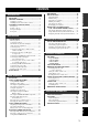
CONTENTS FEATURES............................................................. 2 GETTING STARTED............................................ 3 Supplied accessories .................................................. 3 Installing batteries in the remote control ................... 3 CONTROLS AND FUNCTIONS ......................... 4 Automatic tuning ..................................................... 46 Manual tuning.......................................................... 47 Automatic preset tuning.....
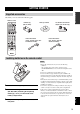
FEATURES FEATURES Built-in 6-channel power amplifier iPod controlling capability ◆ Minimum RMS output power (0.
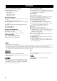
GETTING STARTED GETTING STARTED INTRODUCTION Supplied accessories Check that you received all of the following parts. Remote control CODE SET Batteries (2) (AA, R6, UM-3) TRANSMIT POWER POWER TV AV CD CD-R STANDBY POWER MD AM loop antenna 75-ohm/300-ohm antenna adapter (U.K. model only) SLEEP MULTI CH IN CBL DVD DTV TUNER V-AUX DVR TV VOL TV CH VOLUME TV MUTE TV INPUT MUTE MUSIC ENTERTAIN AMP SOURCE TV STEREO MOVIE 1 2 3 4 STANDARD SELECT EXTD SUR. DIRECT ST.
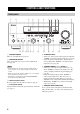
CONTROLS AND FUNCTIONS CONTROLS AND FUNCTIONS Front panel 1 3 2 4 5 6 7 8 A 9 0 VOLUME ZONE 2 ON/OFF ZONE CONTROL MASTER PRESET/TUNING FM/AM EDIT ON A/B/C/D/E l PRESET/TUNING h MEMORY TUNING MODE NEXT LEVEL MAN'L/AUTO FM AUTO/MAN'L OFF PROGRAM INPUT MAIN ZONE PHONES SPEAKERS A B STRAIGHT TONE CONTROL MULTI CH INPUT INPUT MODE VIDEO AUX VIDEO ON/OFF L AUDIO R PORTABLE EFFECT SILENT CINEMA B C DE F G H 1 MASTER ON/OFF Turns on or off this unit (see page 28).
CONTROLS AND FUNCTIONS 9 ZONE 2 ON/OFF Turns on Zone 2 or sets it to the standby mode (see page 90). Note This button is operational only when MASTER ON/OFF is pressed inward to the ON position. 0 ZONE CONTROL Switches the zone you want to control between the main zone and Zone 2 (see page 90). y When Zone 2 is selected, the ZONE2 indicator flashes in the front panel display for approximately 5 seconds. While the indicator is flashing, perform the desired operation.
CONTROLS AND FUNCTIONS Remote control This section describes the function of each control on the remote control used to control this unit. To operate other components, see “REMOTE CONTROL FEATURES” on page 84. Note The operation mode of the remote control buttons in the shaded areas below depends on the component selector switch position. Set the component selector switch to AMP to control this unit.
CONTROLS AND FUNCTIONS B POWER Turns on this unit (see page 28). I NIGHT Turns on or off the night listening modes (see page 34). Note J SET MENU Enters “SET MENU” (see page 71). Note This button is operational only when MASTER ON/OFF on the front panel is pressed inward to the ON position. C SLEEP Sets the sleep timer (see page 35). D MULTI CH IN Selects the component connected to the MULTI CH INPUT jacks as the input source when using an external decoder, etc. (see page 38).
CONTROLS AND FUNCTIONS ■ Controlling the TUNER functions ■ Using the remote control Set the component selector switch to SOURCE and then press TUNER to select “TUNER” as the input source. The remote control transmits a directional infrared ray. Be sure to aim the remote control directly at the remote control sensor on this unit during operation. 4 Numeric buttons Use numbers 1 through 8 to select preset stations. 7 BAND Switches the reception band between FM and AM (see page 46).
CONTROLS AND FUNCTIONS Front panel display t 7 8 9 0 A DOCK VIRTUAL STANDARD SP SILENT CINEMA A B ZONE2 NIGHT VOLUME AUTO TUNED STEREO MEMORY HiFi DSP PTY HOLD PS PTY RT CT EON SLEEP dB MUTE 96/24 LFE ft q DIGITAL q PL x q PL C B pDVR pV-AUX pDTV/CBL pDVD pMD/CD-R pTUNER pCD 96 24 MATRIX DISCRETE ENHANCER q EX 5 6 INTRODUCTION 2 3 4 1 q PL mS dB PCM E D F G H I J K L C R SL SB SR L M N Q O P (U.K.
CONTROLS AND FUNCTIONS F SP A B indicators Light up according to the set of front speakers selected. G Headphones indicator Lights up when headphones are connected (see page 34). H ZONE2 indicator Lights up when Zone 2 is turned on (see page 90). I NIGHT indicator Lights up when you select a night listening mode (see page 34). J HiFi DSP indicator Lights up when you select a HiFi DSP sound field program (see page 58).
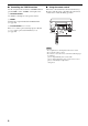
CONTROLS AND FUNCTIONS Rear panel 2 AUDIO 3 AUDIO 45 6 MULTI CH INPUT OUTPUT 7 DIGITAL OUTPUT CENTER MD/CD-R 8 DIGITAL INPUT MD/CD-R DVD DTV/CBL 9 INTRODUCTION 1 DOCK DVD COMPONENT VIDEO DVD Y MD/ OUT (PLAY) CD-R (REC) IN CD DVD DTV/CBL IN DVR OUT VIDEO TUNER AM ANT GND MONITOR OUT DVD FRONT IN DTV/CBL SURROUND DVR OUT S VIDEO SUB WOOFER ZONE 2 SUB WOOFER OPTICAL OPTICAL PB DVR PR Y PB PR COAXIAL MONITOR OUT DTV/CBL MONITOR OUT SPEAKERS FM ANT 75Ω UNBAL.
CONNECTIONS CONNECTIONS Placing speakers The speaker layout below shows the standard ITU-R* speaker setting. You can use it to enjoy CINEMA DSP and multi-channel audio sources. * ITU-R is the radio communication sector of the ITU (International Telecommunication Union). FL Center speaker (C) The center speaker is for the center channel sounds (dialog, vocals, etc.). If for some reason it is not practical to use a center speaker, you can do without it.
CONNECTIONS Connecting speakers Be sure to connect the left channel (L), right channel (R), “+” (red) and “–” (black) properly. If the connections are faulty, no sound will be heard from the speakers, and if the polarity of the speaker connections is incorrect, the sound will be unnatural and lack bass. CAUTION Notes • A speaker cord is actually a pair of insulated cables running side by side. Cables are colored or shaped differently, perhaps with a stripe, groove or ridge.
CONNECTIONS FRONT terminals Connect one or two front speaker systems (1, 2) to these terminals. If you use only one front speaker system, connect it to the FRONT A or B terminal. CENTER terminals Connect a center speaker (3) to these terminals. SURROUND terminals Connect surround speakers (4, 5) to these terminals. SURROUND BACK terminals Connect a surround back speaker (6) to these terminals.
CONNECTIONS ■ Connecting the speaker cable ■ Connecting the banana plug (except U.K., Europe and Asia models) 1 The banana plug is a single-pole electrical connector widely used to terminate speaker cables. Remove approximately 10 mm of insulation from the end of each speaker cable and then twist the exposed wires of the cable together to prevent short circuits. Banana plug 10 mm 2 Insert the banana plug connector into the end of the corresponding terminal. Loosen the knob.
CONNECTIONS Information on jacks and cable plugs Note You can use the digital jacks to input PCM, Dolby Digital and DTS bitstreams. When you connect components to both the COAXIAL and OPTICAL jacks, priority is given to the signals input at the COAXIAL jack. All digital input jacks are compatible with 96-kHz sampling digital signals.
CONNECTIONS Audio and video signal flow ■ Audio signal flow for AUDIO OUT (REC) Input Output AUDIO OUT (REC) DIGITAL AUDIO COAXIAL Digital audio L R L PREPARATION DIGITAL AUDIO OPTICAL R AUDIO Analog audio PORTABLE Digital output Analog output Note This unit handles digital and analog signals independently. Thus, audio signals input at the analog jacks are output only at the analog AUDIO OUT (REC) jacks.
CONNECTIONS Connecting a TV Connect your TV to the VIDEO MONITOR OUT jack, the S VIDEO MONITOR OUT jack or the COMPONENT VIDEO MONITOR OUT jacks of this unit. CAUTION Do not connect this unit or other components to the AC power supply until all connections between components are complete.
CONNECTIONS Connecting a DVD player, a DVD recorder, a VCR or an STB Connect your DVD player, DVD recorder, VCR or STB (set-top box) using the same type of video connections as those made for your TV (see page 18). The cable TV receiver and the satellite receiver are examples of the STB. CAUTION Do not connect this unit or other components to the AC power supply until all connections between components are complete. Notes PREPARATION • When “VIDEO CONV.
CONNECTIONS ■ Connecting a DVD recorder or a VCR AUDIO COMPONENT VIDEO DVR Y DVR OUT IN L V V S S-video in R S-video out L Video out Audio in Audio out R DVR OUT S VIDEO Video in IN VIDEO PB S Y PB PR Component video out DVD recorder or VCR ■ Connecting an STB Cable TV receiver or satellite receiver S O AUDIO Optical audio out V S-video out L Video out R Audio out Component video out Y PB PR DIGITAL INPUT DTV/CBL COMPONENT VIDEO Y PB OPTICAL DTV/CBL VIDEO 20
CONNECTIONS Connecting a CD player, an MD player or a tape deck Connect your CD player, MD player or tape deck via analog and/or digital connections. CAUTION Do not connect this unit or other components to the AC power supply until all connections between components are complete.
CONNECTIONS Connecting a YAMAHA iPod universal dock This unit is equipped with the DOCK terminal on the rear panel that allows you to connect a YAMAHA iPod universal dock (such as YDS-10 sold separately) where you can station your iPod and control playback of your iPod using the supplied remote control. Connect a YAMAHA iPod universal dock (such as YDS-10 sold separately) to the DOCK terminal on the rear panel of this unit using its dedicated cable.
CONNECTIONS Connecting a multi-format player or an external decoder This unit is equipped with 6 additional input jacks (FRONT L/R, CENTER, SURROUND L/R and SUBWOOFER) for discrete multi-channel input from a multi-format player, external decoder or sound processor. Connect the output jacks on your multi-format player or external decoder to the MULTI CH INPUT jacks. Be sure to match the left and right output jacks to the left and right input jacks for the front and surround channels.
CONNECTIONS Connecting the FM and AM antennas Both FM and AM indoor antennas are supplied with this unit. In general, these antennas should provide sufficient signal strength. Connect each antenna correctly to the designated terminals. 2 Press and hold the tab of the AM ANT terminal. 3 Insert one of the AM loop antenna lead wires into the AM ANT terminal. 4 Release the tab of the AM ANT terminal back into place. 5 Repeat steps 2 through 4 to connect the other lead wire to the GND terminal.
CONNECTIONS ■ Assembling the 75-ohm/300-ohm antenna adapter (U.K. model only) Open the cover of the supplied 75-ohm/300ohm antenna adapter. 2 Cut the external sleeve of the 75-ohm coaxial cable to prepare it for connection. PREPARATION 1 11 mm 8 mm 6 mm 3 Cut the lead wire and remove it. Lead wire 4 Insert the cable wire into the slot and then clamp it with pliers. Clamp Clamp Insert the cable wire into the slot. 5 Snap the cover back into place.
CONNECTIONS Connecting the power cable Once all connections are complete, plug the power cable into the AC wall outlet. (U.S.A. model) AC OUTLETS To the AC wall outlet ■ VOLTAGE SELECTOR (Asia and General models only) CAUTION The VOLTAGE SELECTOR on the rear panel of this unit must be set for your local voltage BEFORE plugging the power cable into the AC wall outlet. Improper setting of the VOLTAGE SELECTOR may cause damage to this unit and create a potential fire hazard.
CONNECTIONS Setting the speaker impedance CAUTION 4 If you are to use 4 or 6 ohm speakers, set “SP IMP.” to “6ΩMIN” as follows BEFORE using this unit. Press STRAIGHT (EFFECT) on the front panel repeatedly to select “6ΩMIN”. The following display appears in the front panel display.
CONNECTIONS Turning on and off the power When all connections are complete, turn on this unit.
BASIC SETUP BASIC SETUP The “BASIC SETUP” feature is a useful way to set up your system quickly and with minimal effort. Notes • Make sure you disconnect your headphones from this unit. • If you wish to configure this unit manually using more precise adjustments, use the detailed parameters in “SOUND MENU” (see page 72). • Altering any parameters in “BASIC SETUP” resets all parameters manually adjusted in “SOUND MENU” (see page 72). • Initial settings are indicated in bold under each parameter.
BASIC SETUP 6 Press d to select “SUBWOOFER” and then j / i to select the desired setting. PRESET/CH 8 Press d to select “SETUP” and then j / i to select the desired setting. PRESET/CH ;BASIC SETUP ROOM: S >M L . SUBWOOFER;;;;YES SPEAKERS;;;;6spk SETUP:>OK CANCEL ENTER ;BASIC SETUP ROOM: S >M L SUBWOOFER;;;;YES SPEAKERS;;;;6spk . SETUP:>OK CANCEL ENTER A/B/C/D/E A/B/C/D/E p p [ ]/[ ]:Up/Down [<]/[>]:Select Choices: YES, NONE • Select “YES” if you have a subwoofer in your system.
BASIC SETUP 10 Press j / i to select the desired setting. 12 ;BASIC SETUP PRESET/CH ROOM: S >M L SUBWOOFER;;;;YES SPEAKERS;;;;6spk SETUP:>OK CANCEL . CHECK OK?;;;;YES ENTER A/B/C/D/E p p [ ]/[ ]:Up/Down [<]/[>]:Select PRESET/CH ;BASIC SETUP A/B/C/D/E p • Select “FR” to adjust the balance between the front left and right speakers. • Select “C” to adjust the balance between the front left and center speakers.
PLAYBACK PLAYBACK CAUTION Extreme caution should be exercised when you play back CDs encoded in DTS. If you play back a CD encoded in DTS on a DTS-incompatible CD player, you will only hear some unwanted noise that may damage your speakers. Check whether your CD player supports CDs encoded in DTS. Also, check the sound output level of your CD player before you play back a CD encoded in DTS.
PLAYBACK 5 Rotate VOLUME on the front panel (or press VOLUME +/– on the remote control) to adjust the volume to the desired output level. VOLUME or VOLUME 7 Rotate the PROGRAM selector on the front panel (or press one of the sound field program selector buttons on the remote control repeatedly) to select the desired sound field program. The name of the selected sound field program appears in the front panel display and in the OSD. See page 58 for details about sound field programs.
USING AUDIO FEATURES USING AUDIO FEATURES Using SILENT CINEMA SILENT CINEMA allows you to enjoy multi-channel music or movie sound, including Dolby Digital and DTS sources, through ordinary headphones. SILENT CINEMA activates automatically whenever you connect headphones to the PHONES jack while listening to CINEMA DSP or HiFi DSP sound field programs (see page 58). When activated, the SILENT CINEMA indicator lights up in the front panel display.
USING AUDIO FEATURES y AUTO “NIGHT:CINEMA” and “NIGHT:MUSIC” adjustments are stored independently. Notes DTS • You cannot use the night listening modes in the following cases: – when the “DIRECT STEREO” mode (see page 39) is selected. – when the component connected to the MULTI CH INPUT jacks is selected as the input source (see page 38). – when headphones are connected to the PHONES jack.
USING AUDIO FEATURES 3 Press SLEEP on the remote control repeatedly to set the amount of time. Each time you press SLEEP, the front panel display changes as shown below. SLEEP Adjusting the speaker level You can adjust the output level of each speaker while listening to a music source. This is also possible when playing sources input at the MULTI CH INPUT jacks. Note This operation will override the level adjustments made in “BASIC SETUP” (see page 29) and “SPEAKER LEVEL” (see page 74).
USING AUDIO FEATURES 2 Press j / i on the remote control to adjust the speaker output level. • Press i to increase the value. • Press j to decrease the value. Control range: –10 dB to +10 dB PRESET/CH ENTER A/B/C/D/E 3 Press ENTER on the remote control when you have completed your adjustment.
USING AUDIO FEATURES 1 Set the component selector switch to AMP and then press ENHANCER on the remote control repeatedly to select the desired Compressed Music Enhancer mode. The following display is shown in the OSD and the ENHANCER indicator lights up in the front panel display. AMP ENHANCER SOURCE 0 Selecting the MULTI CH INPUT component Use this feature to select the component connected to the MULTI CH INPUT jacks (see page 23) as the input source.
USING AUDIO FEATURES Enjoying multi-channel sources in 2-channel stereo You can mix down multi-channel sources to 2 channels and enjoy playback in 2-channel stereo. Set the component selector switch to AMP and then press STEREO on the remote control repeatedly to select “2ch Stereo”. Enjoying pure hi-fi stereo sound The “DIRECT STEREO” mode allows sources to bypass the decoders and DSP processors of this unit so that you can enjoy pure hi-fi sound from 2-channel PCM and analog sources.
USING VIDEO FEATURES USING VIDEO FEATURES Signal format FORMAT Signal format display. When this unit cannot detect a digital signal, it automatically switches to analog input. Display status: Analog, Digital, Dolby D, DTS, PCM, --- Displaying the input source information You can display the format, sampling frequency, channel, bit rate and flag data of the current input signal. 1 Note Set the component selector switch to AMP and then press SET MENU on the remote control.
USING VIDEO FEATURES Selecting the OSD mode You can display the operating information of this unit on a video monitor. If you display the “SET MENU” and sound field program parameter settings on a video monitor, it is much easier to see the available options and parameters than it is to read the information in the front panel display. 1 Turn on the video monitor connected to this unit.
ENJOYING SURROUND SOUND ENJOYING SURROUND SOUND Enjoying multi-channel sources in surround If you connected a surround back speaker, use this feature to enjoy 6.1-channel playback for multi-channel sources using the Dolby Pro Logic IIx, Dolby Digital EX or DTS-ES decoders. 1 Set the component selector switch to AMP and then press EXTD SUR. on the remote control repeatedly to switch between 5.1 and 6.1-channel playback.
ENJOYING SURROUND SOUND Enjoying 2-channel sources in surround Signals input from 2-channel sources can also be played back on multi-channels. 1 Set the component selector switch to AMP and then press STANDARD on the remote control repeatedly to switch between the “SUR. STANDARD” and “SUR. ENHANCED” programs or press MOVIE to select the “MOVIE THEATER” program. SUR.
ENJOYING SURROUND SOUND Using Virtual CINEMA DSP Virtual CINEMA DSP allows you to enjoy the CINEMA DSP programs without surround speakers. It creates virtual speakers to reproduce the natural sound field. If you set “SUR. L/R SP” to “NONE” (see page 73), Virtual CINEMA DSP activates automatically whenever you select a CINEMA DSP sound field program (see page 58). Note Virtual CINEMA DSP will not activate even when “SUR.
RECORDING RECORDING Recording adjustments and other operations are performed from the recording components. Refer to the operating instructions for those components. CAUTION The DTS signal is a digital bitstream. Attempting to digitally record the DTS bitstream will result in noise being recorded. Therefore, if you want to use this unit to record sources encoded in DTS, the following considerations and adjustments need to be made.
FM/AM TUNING FM/AM TUNING There are 2 tuning methods: automatic and manual. Automatic tuning is effective when station signals are strong and there is no interference. If the signal from the station you want to select is weak, tune into it manually. You can also use the automatic and manual preset tuning features to store up to 40 stations (A1 to E8: 8 preset station numbers in each of the 5 preset station groups).
FM/AM TUNING Manual tuning 3 If the signal received from the station you want to select is weak, tune into it manually. Press TUNING MODE (AUTO/MAN’L) so that the AUTO indicator disappears from the front panel display. TUNING MODE Note AUTO/MAN'L Manually tuning into an FM station automatically switches the tuner to monaural reception to increase the signal quality.
FM/AM TUNING Automatic preset tuning 3 You can use the automatic preset tuning feature to store FM stations with strong signals up to 40 (A1 to E8: 8 preset station numbers in each of the 5 preset station groups) of those stations in order. You can then recall any preset station easily by selecting the preset station number. Press and hold MEMORY (MAN’L/AUTO FM) for more than 3 seconds. The preset station number as well as the MEMORY and AUTO indicators flashes.
FM/AM TUNING ■ Automatic preset tuning options You can specify the preset number from which this unit stores FM stations and/or begins tuning toward lower frequencies. Note Manual preset tuning You can also store up to 40 stations (A1 to E8: 8 preset station numbers in each of the 5 preset station groups) manually. First carry out steps 1 through 3 in “Automatic preset tuning” on page 48.
FM/AM TUNING 4 Press PRESET/TUNING l / h to select a preset station number (1 to 8) while the MEMORY indicator is flashing. • Press h to select a higher preset station number. • Press l to select a lower preset station number. Selecting preset stations You can tune into any desired station simply by selecting the preset station group and number under which it was stored.
FM/AM TUNING 2 Press PRESET/TUNING l / h on the front panel (or PRESET/CH u / d on the remote control) to select the desired preset station number (1 to 8). The preset station group and number appear in the front panel display along with the station band and frequency. Exchanging preset stations You can exchange the assignments of two preset stations with each other. The example below describes the procedure to exchange preset station “E1” with “A5”.
FM/AM TUNING 3 Select preset station “A5” using A/B/C/D/E and PRESET/TUNING l / h. “A5” and the MEMORY indicator flash in the front panel display. See “Selecting preset stations” on page 50. A/B/C/D/E l PRESET/TUNING h NEXT LEVEL Flashes DVR V-AUX DTV/CBL DVD MD/CD-R pTUNER TUNED CD MEMORY VOLUME SP A dB A5:FM 90.60MHz L R Flashes 4 Press EDIT again. “EDIT E1–A5” appears in the front panel display and the assignments of the two preset stations are exchanged.
RADIO DATA SYSTEM TUNING (U.K. AND EUROPE MODELS ONLY) RADIO DATA SYSTEM TUNING (U.K. AND EUROPE MODELS ONLY) Radio Data System (U.K. and Europe models only) is a data transmission system used by FM stations in many countries. The Radio Data System function is carried out among the network stations.
RADIO DATA SYSTEM TUNING (U.K. AND EUROPE MODELS ONLY) 4 Press PTY SEEK START on the remote control to start searching for all the available Radio Data System preset stations. The name of the selected program type flashes and the PTY HOLD indicator lights up in the front panel display while this unit is searching for stations.
RADIO DATA SYSTEM TUNING (U.K. AND EUROPE MODELS ONLY) 3 Press EON on the remote control repeatedly to select one of the 4 Radio Data System program types (NEWS, AFFAIRS, INFO or SPORT). The name of the selected program type appears in the front panel display. NEWS Displaying the Radio Data System information Use this feature to display the 4 types of the Radio Data System information: PS (program service), PTY (program type), RT (radio text) and CT (clock time).
RADIO DATA SYSTEM TUNING (U.K. AND EUROPE MODELS ONLY) 2 Press FREQ/TEXT on the remote control repeatedly to select the desired Radio Data System display mode. FREQ/TEXT PS PTY RT CT Frequency display • Select “PS” to display the name of the Radio Data System program currently being received. • Select “PTY” to display the type of the Radio Data System program currently being received. • Select “RT” to display the information on the Radio Data System program currently being received.
SOUND FIELD PROGRAMS SOUND FIELD PROGRAMS What really creates the rich, full tones of a live instrument are the multiple reflections from the walls of the room. In addition to making the sound live, these reflections enable us to tell where the player is situated as well as the size and shape of the room in which we are sitting.
SOUND FIELD PROGRAMS Sound field program descriptions This unit is equipped with a variety of precise digital decoders that allow you to enjoy multi-channel playback from almost any stereo or multi-channel sound source. This unit is also equipped with a YAMAHA digital sound field processing (DSP) chip containing several sound field programs which you can use to enhance your playback experience. y The YAMAHA CINEMA DSP modes are compatible with all Dolby Digital, DTS, and Dolby Surround sources.
SOUND FIELD PROGRAMS Remote control button Sound field program Features MOVIE THEATER Spectacle CINEMA DSP processing. This program reproduces the extremely wide sound field of a 70-mm movie theater in detail, making both the video and the sound field incredibly real. This is ideal for any kind of video source encoded in Dolby Surround, Dolby Digital or DTS, especially large-scale movie productions. MOVIE THEATER Sci-Fi CINEMA DSP processing.
SOUND FIELD PROGRAMS Changing sound field parameter settings 2 Turn on the video monitor and then press DISPLAY on the remote control. The following display is shown in the OSD. You can enjoy good quality sound with the initial factory settings. Although you do not have to change the initial factory settings, you can change some of the parameters to better suit the input source or your listening room. DISPLAY Notes • Use the “PARAM.
SOUND FIELD PROGRAMS ■ Sound field parameter descriptions You can adjust the values of certain digital sound field parameters so that the sound fields are recreated accurately in your listening room. Not all of the following parameters are found in every program. y To change sound field parameter settings to suit your listening environment, see page 60 for details. Sound field parameter DSP LEVEL Features DSP level. Adjusts the level of all the DSP effect sounds within a narrow range.
SOUND FIELD PROGRAMS Sound field parameter ROOM SIZE P.ROOM SIZE S.ROOM SIZE SB ROOM SIZE Features Room size. Presence, surround, and surround back room size. Adjusts the apparent size of the surround sound field. The larger the value, the larger the surround sound field becomes. As the sound is repeatedly reflected around a room, the larger the hall is, the longer the time between the original reflected sound and the subsequent reflections.
SOUND FIELD PROGRAMS Sound field parameter REV.TIME Features Reverberation time. Adjusts the amount of time taken for the dense, subsequent reverberation sound to decay by 60 dB at 1 kHz. This changes the apparent size of the acoustic environment over an extremely wide range. Set a longer reverberation time for “dead” sources and listening room environments, and a shorter time for “live” sources and listening room environments. Control range: 1.0 to 5.
SOUND FIELD PROGRAMS Sound field parameter REV.LEVEL Features Reverberation level. Adjusts the volume of the reverberation sound. The larger the value, the stronger the reverberation becomes. Level Control range: 0 to 100% Source sound (dB) 60 dB Reverberation Time REV.DELAY 2ch Stereo DIRECT REV.TIME 2-channel stereo direct. Bypasses the decoders and DSP processors of this unit for pure hi-fi stereo sound when playing 2-channel analog sources.
SOUND FIELD PROGRAMS Sound field parameter Features PRO LOGIC IIx Music PRO LOGIC II Music PANORAMA Pro Logic IIx Music and Pro Logic II Music panorama. Sends stereo signals to the surround speakers as well as the front speakers for a wraparound effect. PRO LOGIC IIx Music PRO LOGIC II Music DIMENSION Pro Logic IIx Music and Pro Logic II Music dimension. Adjusts the sound field either towards the front or towards the rear.
SOUND FIELD PROGRAMS Sound field program speaker layouts Sound output from each speaker depends on the type of audio signals being input. Refer to the diagrams in the table below to understand the speaker layout for each sound field program. Note Be advised that there may be no or not enough sound output from speakers depending on the type of input source being played back.
SOUND FIELD PROGRAMS Sound field program MOVIE THEATER Spectacle Sci-Fi Adventure General 2-channel audio (monaural) L SL SUR. STANDARD DOLBY DIGITAL PRO LOGIC DTS L SL C SB R L SR SL R L SR SL C SB 2-channel audio (stereo) Pro Logic SUR. STANDARD PLII Movie PLII Music PLII Game PLIIx Movie PLIIx Music PLIIx Game L SL C SB C SB R L SR SL R L SR SL C SB 5.1/6.
SOUND FIELD PROGRAMS Sound field program SUR. ENHANCED PLII Movie PLIIx Movie 2-channel audio (monaural) L SL C SB 2-channel audio (stereo) R L SR SL C SB 5.1/6.1-channel audio * R SR Pro Logic II L SL C SB R SR Pro Logic IIx SUR.
SET MENU SET MENU You can use the following parameters in “SET MENU” to adjust a variety of system settings and customize the way this unit operates. Change the initial settings (indicated in bold under each parameter) to reflect the needs of your listening environment. ■ Basic setup BASIC SETUP Use this feature to set up your system quickly and with minimal effort (see page 29). ■ Manual setup MANUAL SETUP Use this feature to manually adjust speaker and system parameters.
SET MENU Option menu 3 OPTION MENU Use this menu to manually adjust the optional system parameters. Parameter Features Page A)DISPLAY SET Adjusts the brightness of the display and converts video signals. 79 B)MEMORY GUARD Locks sound field program parameters and other “SET MENU” settings. 80 C)PARAM. INI Initializes the parameters of a group of sound field programs. 80 D)MULTI ZONE SET Specifies the location of the speakers connected to the SPEAKERS B terminals.
SET MENU Using SET MENU 2 Press u / d to select “MANUAL SETUP”. Use the remote control to access and adjust each parameter. TV AV CD CD-R STEREO MD SLEEP V-AUX DTV ENTERTAIN MOVIE 1 2 3 4 STANDARD SELECT EXTD SUR. DIRECT ST. 5 6 7 8 SPEAKERS ENHANCER NIGHT STRAIGHT 9 0 TUNER DVR ENTER A/B/C/D/E [ ]/[ ]:Up/Down [ENTER]:Enter p DVD MUSIC SET MENU ;BASIC SETUP . ;MANUAL SETUP . ;SIGNAL INFO p MULTI CH IN CBL PRESET/CH ENT.
SET MENU 5 Press u / d repeatedly and then press ENTER to select and enter the desired submenu. The following display is an example where “SPEAKER LEVEL” is selected. PRESET/CH 1 SOUND MENU Use this menu to manually adjust any speaker settings or compensate for video signal processing delays when using LCD monitors or projectors. 1 SOUND MENU 1/2 PRESET/CH ENTER 1 SOUND MENU 2/2 p .
SET MENU Center speaker CENTER SP Choices: NONE, SML, LRG CENTER SP Surround back speakers SUR. B SP Choices: NONE, SML, LRG SUR. B SP NONE >SML LRG NONE >SML LRG • Select “NONE” (none) if you did not connect a center speaker. The low-frequency signals of the center channel are directed to the speakers selected in “LFE/ BASS OUT”, and the rest of the center channel signals are directed to the front left and right speakers.
SET MENU Crossover CROSS OVER Use this feature to select a crossover frequency of all the speakers set to “SML” (or “SMALL”) or to “NONE” in “SPEAKER SET” (see pages 72 and 73). All frequencies below the selected frequency will be sent to the subwoofer or to the speakers set to “LRG” (or “LARGE”) in “SPEAKER SET” (see pages 72 and 73).
SET MENU ■ Speaker distance C)SP DISTANCE ■ Center graphic equalizer D)CENTER GEQ Use this feature to manually adjust the distance of each speaker and the delay applied to the respective channel. Ideally, each speaker should be the same distance from the main listening position. However, this is not possible in most home situations. Thus, a certain amount of delay must be applied to the sound from each speaker so that all sounds will arrive at the listening position at the same time.
SET MENU ■ Dynamic range F)DYNAMIC RANGE Use this feature to select the amount of dynamic range compression to be applied to your speakers or headphones. This setting is effective only when this unit is decoding Dolby Digital and DTS signals. ■ Audio settings G)AUDIO SET Use this feature to adjust the overall audio settings of this unit. G)AUDIO SET F)DYNAMIC RANGE p [ ]/[ ]:Up/Down [<]/[>]:Select p . SP: MIN STD>MAX HP: MIN STD>MAX .
SET MENU 2 INPUT MENU Use this menu to reassign the input/output jacks, select the input mode or rename the input source. 2 INPUT MENU p p .
SET MENU ■ Input mode B)INPUT MODE Use this feature to set this unit to reset “INPUT MODE” back to “AUTO” (see page 35) regardless of the previous setting or to recall the last input mode (“AUTO”, “DTS”, or “ANALOG”) used for that source whenever you turn on this unit. Choices: AUTO, LAST 2 Set the component selector switch to AMP and then press j / i on the remote control to place the “_” (underscore) under the space or the character you want to edit.
SET MENU ■ Volume Trim D)VOLUME TRIM Use this menu to adjust the optional system parameters. 3 OPTION MENU . A)DISPLAY SET B)MEMORY GUARD C)PARAM. INI D)MULTI ZONE SET [ ]/[ ]:Up/Down [ENTER]:Enter p D)VOLUME TRIM DVD -> 0.0dB 3 OPTION MENU p Use this feature to adjust the level of the signal input at each jack. This is useful if you want to balance the level of each input source to avoid sudden changes in volume when switching between input sources.
SET MENU OSD shift OSD SHIFT Use this feature to adjust the vertical position of the OSD. Control range: –5 (upward) to +5 (downward) Control step: 1 Initial setting: 0 • Press j to raise the position of the OSD. • Press i to lower the position of the OSD. Gray back GRAY BACK Use this feature to display a gray background in the OSD when there is no video signal being input. Choices: AUTO, OFF • Select “AUTO” to display a gray background in the OSD when there is no video signal being input.
SET MENU ■ Zone set D)MULTI ZONE SET Use this feature to specify the location of speakers connected to the SPEAKERS B terminals of this unit. D)MULTI ZONE SET . SP B;;;;;;;FRONT [<]/[>]:Select [ENTER]:Return Speaker B setting SP B Use this feature to select the location of the front speakers connected to the SPEAKERS B terminals.
ADVANCED SETUP ADVANCED SETUP This unit has additional menus that are displayed in the front panel display. The advanced setup menu offers additional operations to adjust and customize the way this unit operates. Change the initial settings (indicated in bold under each parameter) to reflect the needs of your listening environment. Notes • The settings you make are reflected next time you press MASTER ON/OFF inward to the ON position to turn on this unit (see page 28).
ADVANCED SETUP ■ Speaker impedance SP IMP. Use this feature to set the speaker impedance of this unit so that it matches that of your speakers. Choices: 8ΩMIN, 6ΩMIN • Select “8ΩMIN” to set the speaker impedance to 8 Ω . • Select “6ΩMIN” to set the speaker impedance to 6 Ω . SP IMP. Speaker Impedance level If you use one set (A or B), the impedance of each speaker must be 8 Ω or higher. Front If you use two sets (A and B), the impedance of each speaker must be 16 Ω or higher.
REMOTE CONTROL FEATURES REMOTE CONTROL FEATURES In addition to controlling this unit, the remote control can also operate other audiovisual components made by YAMAHA and other manufacturers. To control your TV or other components, you must set the appropriate remote control code for each input source (see page 86). Controlling this unit, a TV, or other components ■ Controlling this unit ■ Controlling a TV Set the component selector switch to AMP to control this unit.
REMOTE CONTROL FEATURES ■ Controlling other components Set the component selector switch to SOURCE to control other components selected with the input selector buttons, , , or the blank button on the right of MD/CD-R. You must set the appropriate remote control code for each input source (see page 86). The following table shows the function of each control button used to control other components assigned to each input selector button, , , and the blank button on the right of MD/CD-R.
REMOTE CONTROL FEATURES Setting the remote control code 1 You can control your TV and other components by setting the appropriate remote control code for each input source. For a complete list of available remote control codes, refer to “LIST OF REMOTE CONTROL CODES” at the end of this manual. Press one of the input selector buttons or / to select the component you want to set up.
REMOTE CONTROL FEATURES ■ Setting remote control TUNER ID library codes Setting library codes You can operate multiple YAMAHA receivers or amplifiers in the same room with the supplied remote control simultaneously. Set the appropriate library code to select and operate the desired component with the supplied remote control. Select one of the following codes to set the remote control TUNER ID library code for the component you want to use.
REMOTE CONTROL FEATURES Resetting all remote control codes Use this feature to clear all the remote control codes previously set and reset all of them to the initial factory settings. 1 Press CODE SET using a ballpoint pen or a similar object. The TRANSMIT indicator on the remote control flashes twice. TRANSMIT CODE SET Flashes 2 Press the numeric buttons to enter the code number “9981”.
USING MULTI-ZONE CONFIGURATION USING MULTI-ZONE CONFIGURATION This unit allows you to configure a multi-zone audio system. The Zone 2 feature allows you to set this unit to reproduce separate input sources in the main zone and the second zone (Zone 2). You can control this unit from the second zone using the supplied remote control. Only analog signals are sent to the second zone. Any source you want to listen to in the second zone must be connected to the analog AUDIO IN jacks of this unit.
USING MULTI-ZONE CONFIGURATION Controlling Zone 2 You can select and control Zone 2 by using the control buttons on the front panel or on the remote control.
USING MULTI-ZONE CONFIGURATION ■ Setting the remote control to the Zone 2 mode 1 Note The remote control is originally set to the main mode to control the main zone. To control Zone 2 with the remote control, you must first set the remote control to the Zone 2 mode. 1 Press CODE SET using a ballpoint pen or a similar object. The TRANSMIT indicator on the remote control flashes twice. Press and hold POWER or STANDBY and then press to set the remote control to the Zone 2 mode.
USING IPOD® USING iPod® Once you have stationed your iPod in a YAMAHA iPod universal dock (such as YDS-10 sold separately) connected to the DOCK terminal of this unit (see page 22), you can enjoy playback of your iPod using the supplied remote control. You can also use the Compressed Music Enhancer mode of this unit to improve the sound quality of the compression artifacts (such as the MP3 format) stored on your iPod (see page 37).
USING iPod® ■ Controlling iPod using the OSD Once “V-AUX” is selected as the input source, you can perform the advanced operations of your iPod using the supplied remote control with the aid of the OSD of this unit. You can also browse the songs stored on your iPod in the OSD. Further, you can change or adjust settings for your iPod to suit your personal preferences. Notes • Operations cannot be done with the controls on your iPod. • The YAMAHA logo appears in the display window of your iPod.
RESETTING THE SYSTEM RESETTING THE SYSTEM Use this feature to reset all the parameters of this unit to the initial factory settings. Notes • This procedure completely resets all the parameters of this unit including the “SET MENU” parameters. However, the advanced setup menu parameters will not be initialized. • The initial factory settings are activated next time you turn on this unit.
TROUBLESHOOTING TROUBLESHOOTING Refer to the table below when this unit does not function properly. If the problem you are experiencing is not listed below or if the instruction below does not help, turn off this unit, disconnect the power cable, and contact the nearest authorized YAMAHA dealer or service center. ■ General Problem This unit fails to turn on or enters the standby mode soon after the power is turned on.
TROUBLESHOOTING Problem The sound suddenly goes off. Cause See page Check that the speaker impedance setting is correct. 27, 83 Check that the speaker wires are not touching each other and then turn this unit back on. — The sleep timer has turned off this unit. Turn on this unit, and play the source again. — The sound is muted. Press MUTE or VOLUME +/– on the remote control to resume audio output. 34 Sound is heard from the speaker on one side only. Incorrect cable connections.
TROUBLESHOOTING Problem Cause Remedy See page Dolby Digital or DTS sources cannot be played. (Dolby Digital or DTS indicator in the front panel display does not light up.) The connected component is not set to output Dolby Digital or DTS digital signals. Make an appropriate setting following the operating instructions for your component. — “INPUT MODE” is set to “ANALOG”. Set “INPUT MODE” to “AUTO” or “DTS”. 35 A humming sound is heard. Incorrect cable connections.
TROUBLESHOOTING ■ Tuner Problem FM stereo reception is noisy. FM AM 98 Cause The characteristics of FM stereo broadcasts may cause this problem when the transmitter is too far away or the antenna input is poor. Remedy See page Check the antenna connections. 24 Try using a high-quality directional FM antenna. — Use the manual tuning method. 47 There is distortion, and clear reception cannot be obtained even with a good FM antenna. There is multi-path interference.
TROUBLESHOOTING ■ Remote control Problem The remote control does not work nor function properly. Cause Remedy See page Wrong distance or angle. The remote control functions within a maximum range of 6 m and no more than 30 degrees off-axis from the front panel. 8 Direct sunlight or lighting (from an inverter type of fluorescent lamp, etc.) is striking the remote control sensor of this unit. Reposition this unit. — The batteries are weak. Replace all batteries.
GLOSSARY GLOSSARY Audio information ■ Dolby Digital Dolby Digital is a digital surround sound system that gives you completely independent multi-channel audio. With 3 front channels (front L/R and center), and 2 surround stereo channels, Dolby Digital provides 5 full-range audio channels. With an additional channel especially for bass effects, called LFE (Low Frequency Effect), the system has a total of 5.1-channels (LFE is counted as 0.1 channel).
GLOSSARY ■ LFE 0.1 channel This channel reproduces low-frequency signals. The frequency range of this channel is from 20 Hz to 120 Hz. This channel is counted as 0.1 because it only enforces a low-frequency range compared to the full-range reproduced by the other 5/6 channels in Dolby Digital or DTS 5.1/6.1-channel systems. ■ Neo:6 Neo:6 decodes the conventional 2-channel sources for 6channel playback by the specific decoder.
GLOSSARY Sound field program information ■ CINEMA DSP Since the Dolby Surround and DTS systems were originally designed for use in movie theaters, their effect is best felt in a theater having many speakers designed for acoustic effects. Since home conditions, such as room size, wall material, number of speakers, and so on, can differ so widely, it is inevitable that there are differences in the sound heard.
SPECIFICATIONS SPECIFICATIONS AUDIO SECTION VIDEO SECTION • Minimum RMS Output Power for Front, Center, Surround, Surround back 20 Hz to 20 kHz, 0.06% THD, 8 Ω ....................................... 95 W • Video Signal Type .......................................................... PAL/NTSC • Maximum Power (EIAJ) [Asia, China, Korea and General models] 1 kHz, 10% THD, 8 Ω ..........................................................135 W • Dynamic Power (IHF) 8/6/4/2 Ω ...................................
01EN_07_Code_RX-V559_G.
01EN_07_Code_RX-V559_G.
01EN_07_Code_RX-V559_G.
01EN_07_Code_RX-V559_G.
01EN_07_Code_RX-V559_G.
01EN_07_Code_RX-V559_G.
01EN_07_Code_RX-V559_G.
01EN_07_Code_RX-V559_G.
01EN_07_Code_RX-V559_G.
01EN_07_Code_RX-V559_G.
01EN_07_Code_RX-V559_G.
01EN_07_Code_RX-V559_G.
RX-V559_G_cv.fm Page 1 Tuesday, November 22, 2005 3:43 PM G RX-V559 © 2006 YAMAHA ELECTRONICS CORPORATION, USA 6660 ORANGETHORPE AVE., BUENA PARK, CALIF. 90620, U.S.A. YAMAHA CANADA MUSIC LTD. 135 MILNER AVE., SCARBOROUGH, ONTARIO M1S 3R1, CANADA YAMAHA ELECTRONIK EUROPA G.m.b.H. SIEMENSSTR. 22-34, 25462 RELLINGEN BEI HAMBURG, GERMANY YAMAHA ELECTRONIQUE FRANCE S.A. RUE AMBROISE CROIZAT BP70 CROISSY-BEAUBOURG 77312 MARNE-LA-VALLEE CEDEX02, FRANCE YAMAHA ELECTRONICS (UK) LTD.