How to Use This Reference Manual The CL5/CL3/CL1 V5 Reference Manual (this document) allows you to search for terms and take advantage of links in the text. Searching for terms To search for a term, use the search function of the software you’re using to view this document. If you’re using Adobe Reader, enter the term in the search box and press the key of your computer keyboard to search for occurrences of that term.
Contents Contents Using dynamics ...................................................................................................... 69 Using the EQ/Dynamics libraries ............................................................................. 73 Channel Job ............................................................................. 74 How to Use This Reference Manual .......................................................................... 1 DCA group ..........................................
Contents I/O devices and external head amps .................................... 173 Using an I/O device ............................................................................................. Remotely controlling an R series unit ................................................................... Third-party equipment’s HA control function....................................................... Remotely controlling an amp...............................................................................
Function Tree Function Tree MIX SEND/MATRIX SEND Page numbers in parentheses ( ) are the page numbers of the Owner’s Manual(booklet).
Function Tree SETUP WORD CLOCK/SLOT SETUP CASCADE IN/OUT PATCH OUTPUT PORT MIDI/GPI PATCH 246 249, 251 63 26, 28, 117, 125, 174, 250 PORT SELECT CH SELECT 23, 142, 201 192, 271 MIDI SETUP 193 PROGRAM CHANGE 195 Others CONTROL CHANGE 198 CONFIRMATION 223 GPI 271 SOFT KEYBORD (21) FADER START 274 LOGIN 218 BUS SETUP 252 SURROUND SETUP 214 Startup Menu CONSOLE LOCK 238 MODE SELECT DATE/TIME 254 INITIALIZE ALL MEMORIES 278 NETWORK 255 INITIALIZE CURRENT MEMORIES 278 DANTE
SELECTED CHANNEL section SELECTED CHANNEL section • Even if a different screen is selected, the channel selected with the [SEL] key can be set using the knobs of the SELECTED CHANNEL section. In this case, a window indicating the value of that parameter will appear on screen when you operate a knob.
SELECTED CHANNEL section SELECTED CHANNEL VIEW screen If the destination bus channels are two mono channels: 1 2 3 1 SEND knob Adjusts the send level to the corresponding bus. 2 PRE indicator The type of the corresponding bus is indicated. If the type is VARI [PRE EQ] or VARI [PRE FADER], and if the PRE button on the MIX SEND 8ch screen is turned ON, the type is displayed. 3 ON button Switches the send signal to the corresponding bus on or off.
SELECTED CHANNEL section When using CUE B Indicates that channels 7 and 8 on the MATRIX bus are combined with CUE B. If patched to a wireless mic (SELECTED CHANNEL VIEW screen) 1 RX.GAIN knob/TX.GAIN knob/TX.ATT knob NOTE For details about how to use CUE B, see the CUE screen (When configuring CUE B). When remote control connection is disabled for the connected device, a gray circle is displayed here instead of a knob, and the gain cannot be adjusted.
SELECTED CHANNEL section PAN/BALANCE field When using Surround mode (MIX1- MIX6) This field enables you to switch the on/off status of the signal sent from the selected channel to the STEREO/MONO bus, and adjust the pan and balance. The view and the function of the controllers in this field vary depending on the type of the selected channel. 3 DOWN MIX This field enables you to view the downmix coefficient and L/R button settings. Press this field to open the TO STEREO/MONO window.
SELECTED CHANNEL section EQ parameter field EQ graph field This field displays the 4-band EQ parameter settings. Press each knob to open the HPF/EQ 1ch window. This field graphically indicates the approximate response of the EQ. Press this field to open the HPF/EQ 1ch window, in which you can set the attenuator, HPF, and EQ. 1 Q knob Specifies the Q for each band. If the HIGH band filter type is set to LPF or H.SHELF (highshelving), or the LOW band filter type is set to L.
SELECTED CHANNEL section INSERT field FADER field 1 This field enables you to make insert settings. This field enables you to make settings for the channel on/off status and the level. 1 Popup button 2 ON button 3 2 1 Fader 2 Press this button to open the INSERT/DIRECT OUT 1ch window. Displays the current level. Use the faders on the top panel to set the levels. 4 2 Level indicator Switches the insert on or off. 1 3 Displays the current level setting by numerical value.
SELECTED CHANNEL section When the mute group tab is selected: 4 Mute group select buttons 5 Select the mute group to which the channel is assigned. NOTE If the dimmer level is set to the mute group, this button lights orange. 5 SAFE button 6 4 Temporarily removes the channel from the mute group. 6 DCA group indicators Indicate the DCA group to which the channel is assigned.
Centralogic section Centralogic section Operations in the Centralogic section The Centralogic section located below the touch screen lets you recall and simultaneously control a set of eight input channels, output channels, or DCA groups. If you press one of the Bank Select keys, the channels or DCA groups corresponding to that key will be assigned to the Centralogic section, and can be controlled using the faders, [ON] keys, and [CUE] keys in the Centralogic section. STEP 1.
Centralogic section GAIN/PATCH field OVERVIEW Screen This field enables you to make HA (head amp) analog or digital gain settings. You can also view the operational status of the head amp. The view and the function of the controllers in this field vary depending on the type of the selected channel. If the head amp is patched: 2 3 4 1 1 GAIN knob Sets the analog gain of the head amp.
Centralogic section If patched to a wireless mic (OVERVIEW screen) 1 If the slot is patched: The slot name will appear. 2 If the rack is connected: The patch and module name will appear. If the output is connected: Only the patch will appear. 34 5 1 RX.GAIN knob/TX.GAIN knob/TX.ATT knob INPUT DELAY field (input channels only) Sets the gain for the transmitter or receiver.
Centralogic section EQ field SEND field This field graphically indicates the approximate response of the EQ. Press this field to open the HPF/EQ 1ch window, in which you can set the HPF and EQ. This field displays the send level, send on/off status, and pre/post settings for 16 buses. To select the 16 destination buses, use the [MIX 1-16] key/[MIX 17-24/ MATRIX] key in the SELECTED CHANNEL section.
Centralogic section TO STEREO/MONO field Mute group field This field displays the on/off status and pan/balance setting of the signal sent to the STEREO/ MONO bus. This field varies depending on the type of the selected channel. A mute group (1-8) to which the channel is assigned is displayed on the third row in this field. If the channel has been temporarily removed from the mute group, S (Safe) will appear on the third row.
Input and output patching Input and output patching Output port (jack/port) This chapter explains how to edit the input patching and output patching, how to connect inserts, and how to use direct outputs. When the CL series is in the initial state, the following input ports (jacks/ports) are patched to each input channel.
Input and output patching Changing the input patching Input patching CL series consoles and I/O devices feature two types of patching: Dante audio network patching and CL console internal patching. For Dante audio network patching, you will use the DANTE INPUT PATCH window. In this window, you can patch the CL console and I/O device inputs. Sixty-four (64) channels can be input from a Dante audio network to a CL series console.
Input and output patching PATCH/NAME screen 2 3 • PREMIUM RACK...PR1L(A) - PR2R(B) 5 Port select buttons 8 Select the input port that is assigned to the currently-selected channel. 6 Channel name/Effect type indicator 1 NOTE In categories other than DANTE IN, channel labels cannot be set in Dante Controller for the following buttons, and therefore they are not displayed.
Input and output patching Changing the output patching PATCH/NAME screen 3 To change the patching, you can either select the output port that will be the output destination of each output channel, or you can select the output channel that will be the output source for each output port. 4 5 9 1 Selecting the output port for each output channel STEP 1. Use the Bank Select keys in the Centralogic section to select the output channels. 2. Press the channel number/channel name field on the OVERVIEW screen.
Input and output patching 7 Port select buttons CH SELECT screen From the category, these buttons let you select the port to patch. To cancel the selection, press the button once again. 8 Tabs Enable you to switch between items. 9 Close button Closes the screen. Selecting the output channel for each output port 2 1 STEP 1. In the Function Access Area, press the SETUP button. 2. Press the OUTPUT PORT button in the SYSTEM SETUP field located in the center of the SETUP screen. 3.
Input and output patching Inserting an external device into a channel NOTE In the case of the CL3/CL1, channels that do not exist on those models will not be shown. You can insert an effect processor or other external device into the signal path of an INPUT, MIX, MATRIX, STEREO, or MONO channel. When doing so, the type of input/output port used for the insertion and the location of the insertion in/out can be specified individually for each channel.
Input and output patching • If you exceed the INSERT OUT or INSERT IN limitation, the INSERT/DIRECT OUT screen (1ch) indicator will light up on the left. 3 < 6 78 < 9 1 2 4 5 INSERT field This field enables you to make insert settings. Press one of three fields to choose PRE EQ (immediately before the EQ), PRE FADER (immediately before the fader), or POST ON (immediately after the [ON] key) as the insert position. NOTE You can set the I/O ports to function as an insert for each block.
Input and output patching INSERT IN HA field INSERT/DIRECT OUT screen (8ch) This field will appear if you have selected an input port (that features a head amp) as the insert-in. 1 6 +48V button Switches head amp phantom power (+48V) (currently-selected for insert 1 and insert 2) on or off. 2 7 A.GAIN knob 3 Indicates the currently-selected head amp analog gain setting for insert 1 and insert 2. Press these knobs to control the parameter values using the multifunction knobs.
Input and output patching PORT SELECT screen Directly outputting an INPUT channel Displayed when you press either the INSERT OUT or INSERT IN button in the one-channel or the eight-channel INSERT/DIRECT OUT window. Set the input/output port used for insertion. The signal of an INPUT channel can be output directly from an OUTPUT jack on the I/O device, from the desired OMNI OUT jack, or from the output channel of a desired slot. STEP 1.
Input and output patching INSERT/DIRECT OUT screen (1ch) INSERT/DIRECT OUT screen (8ch) 4 6 1 2 3 1 2 4 3 5 1 DIRECT ON button Switches the Direct Out on or off. The currently-selected Direct Out point is indicated above the button. 1 DIRECT OUT field Enables you to make settings for direct output.
Input and output patching PORT SELECT screen Displayed when you press the DIRECT OUT PATCH button in the one-channel or the eightchannel INSERT/DIRECT OUT window. Set the output port used for direct output. 2 1 3 1 Category select list Selects the category of output port. The categories correspond to the following output ports. The displayed categories vary depending on the channel type. • OMNI/REC .............OMNI1-OMNI8, REC IN(L), REC IN(R) • SLOT1....................SLOT1(1) - SLOT1(16) • SLOT2.....
Input channels Input channels STEREO channels These channels are used to process stereo signals. When the CL series console is in the default state, the input signal from the EFFECT RACK 1 - 8 is assigned. This chapter explains various operations for input channels.
Input channels Specifying the channel name/icon • Pan Adjusts the panning of signals sent from the input channel to the STEREO bus. For the STEREO channel, you can switch between PAN and BALANCE. The BALANCE parameter adjusts the volume balance of the left/right signals sent from the STEREO channel to the STEREO bus. You can turn on PAN LINK in the BUS SETUP window so that the setting of the PAN parameter will also be applied to signals sent to two MIX or MATRIX buses that are set to stereo.
Input channels When selecting the ICON tab PATCH/NAME screen When selecting the PATCH tab 2 3 5 1 1 2 3 1 Channel color select buttons Select a channel color. 4 2 Icon select buttons Select a channel icon. 1 PATCH button Indicates the currently-patched port. If you press this button when another tab is active, a window will appear, enabling you to select the network and port. 3 Sample name setup buttons Select a preset sample name. You can edit the name on the NAME tab later.
Input channels When selecting the NAME tab HA (head amp) settings You can directly enter a channel name on the keyboard screen. You can make HA (Head Amp) related settings (phantom power on/off, gain, phase) for the input channel. • To adjust only the HA analog gain, use the GAIN knob in the SELECTED CHANNEL section. Setting the gain Head amp settings are made in the GAIN/PATCH window. STEP 1. Use the Bank Select keys in the Centralogic section to select the channels. 2.
Input channels GAIN/PATCH window (1 ch) 1 2 8 3 0 4 • Gain compensation meter Indicates the level of the signal output to the audio network after gain compensation. 9 5 6 2 HA section (If patched to a wireless mic) 7 1 Channel icon/Channel number/Channel name indicator Indicates the channel icon, number, and name. • Frequency Indicates the frequency that is currently set for the RF signal. 2 HA section • Signal quality meter Displays the quality of the received RF signal.
Input channels 3 INPUT PORT button GAIN/PATCH window (8ch) Indicates the port that is assigned to the channel. Press this button to display the PORT SELECT window, in which you can select a port to patch. 7 9 4 Icon / Channel name button Indicates the channel number, icon, and name. Press this button to access the PATCH/ NAME window, in which you can patch the input port and specify the channel name.
Input channels • A.GAIN (analog gain) knob Indicates the analog gain of the head amp. Press this knob to control the parameter values using the multifunction knobs. If the Gain Compensation function is turned on, an indicator appears, showing the analog gain position at the time the function was turned on. PORT SELECT window TAKE FROM CHANNEL button TAKE FROM PORT button • Level meter Indicates the input signal level.
Input channels GAIN/PATCH window (1-48, 49-72/ST IN (CL5), 49-64/ST IN (CL3), ST IN (CL1)) • RF (Radio Frequency) signal meter Shows bars to indicate the level of the RF signal. An active antenna indicator is shown on the right side. It indicates which antenna is enabled by lighting up. This window displays the head amp settings of the corresponding input channels.
Input channels If you press the ANALOG GAIN parameter select button: 1 If you press the PATCH parameter select button: 2 3 4 1 1 PATCH button 1 GAIN knob Press this button to open the PORT SELECT window, in which you can select an input port to patch to the channel. Indicates the analog gain setting for each channel. Press this knob to select a channel, and then control the gain value using the multifunction knob.
Input channels Sending the signal from an input channel to the STEREO/MONO bus Relationship between analog and digital gain while Gain Compensation is on If Gain Compensation is on, adjusting the analog gain by a specific amount will cause the I/O device to output to the audio network a signal that is attenuated by the same amount. Therefore, the signals on the audio network will maintain a constant corrected level in the digital domain.
Input channels STEP 1. Set the phantom power, gain, and phase of the input channel from which you want to send the signal to the STEREO/MONO bus. 2. Use the Bank Select keys in the Centralogic section to select the input channel from which you want to send the signal to the STEREO/MONO bus. 3. In the STEREO/MONO field, press a knob to select the channel you want to adjust in the OVERVIEW screen, and then press the knob once again. 4.
Input channels 7 Tabs TO STEREO/MONO window (8ch) Enable you to switch between windows. Here you can control the on/off and pan/balance settings of the signal sent from input channels to the STEREO (L/R) bus and MONO (C) bus, in groups of eight channels. 8 1 9 2 3 4 8 LCR button If the MODE button is set to LCR mode, this button is displayed instead of 4. This button is an overall on/off button for signals sent from a channel to the STEREO bus and MONO bus.
Input channels 1 PAN LAW select button Added pan function (Monaural input channels only) This toggle button is used to set the PAN LAW for the Input Channel. The pan setting for signals sent to the STEREO bus enables you to select PAN LAW settings. You can select one of the following: CENTER NOMINAL The pan level is nominal at center and +3dB when panned 100% either left or right. LR NOMINAL The pan level is -3dB at center and nominal when panned 100% either left or right.
Input channels TO STEREO/MONO window (CH 1-48, CH 49-72/ST IN (CL5), CH 49-64/ST IN (CL3), ST IN (CL1)) Signal level when LCR mode is selected Adjusts the status of a signal sent from the corresponding input channel to the STEREO/ MONO bus. Here you can also adjust the pan or balance in groups of the selected eight channels.
Input channels When the CSR knob is set to 100% Sending a signal from an input channel to a MIX/ MATRIX bus Signal level Signal sent to the MONO (C) bus The MIX buses are used mainly for the purpose of sending signals to foldback speakers on stage, or to external effect processors. The MATRIX buses are used to produce a mix that is independent of the STEREO bus or MIX buses, and is typically sent to a master recorder or to a backstage monitoring system.
Input channels If the MIX bus is a FIXED type Using the Selected Channel section This section explains how to use the knobs in the SELECTED CHANNEL section to adjust the send levels of signals sent from a specific input channel to all MIX/MATRIX buses. STEP 1. Assign an output port to each MIX/MATRIX bus to which you want to send signals, and connect your monitor system, external effects processor, or other device to the corresponding output port. 2.
Input channels Using the Centralogic section MIX SEND/MATRIX SEND window 3 You can use the multifunction knobs in the Centralogic section to adjust the send level of signals sent from eight consecutive input channels to a specific MIX/MATRIX bus. STEP 1. Assign an output port to each MIX/MATRIX bus to which you want to send signals, and connect your monitor system, external effects, or other device to the corresponding output port. 2.
Input channels 8 SEND PAN/BALANCE knob Sets the panning or balance of signals sent to the stereo send destination. If the send destination is monaural or set to FIXED, this knob will not appear. If the send source is monaural, this knob functions as a PAN knob. If the send source is stereo, you can use PAN/BALANCE mode setting in the TO STEREO/MONO window to select whether PAN/BALANCE will function as a PAN or BALANCE knob. The knob for the mode selected here will appear.
Input channels Channel name display indication SENDS ON FADER mode 1 In SENDS ON FADER mode, ON/OFF is indicated for the channel. CHANNEL ON 3 CHANNEL OFF 2 On the PREFERENCE page in the USER SETUP pop-up window, the channel number is shown if NAME DISPLAY is set to “NAME ONLY”. Channel number display 1 MIX/MTRX ON FADER switch button Use this button to switch between MIX 1-16 and MIX 17-24/MATRIX for the bus displayed in the Function Access Area.
Input channels Correcting delay between channels (Input Delay) INPUT DELAY screen (8ch) You can set the on/off status and the value of the input channel delay. This section explains how to correct delay between input channels by using the Input Delay function.
Input channels INPUT DELAY (CH 1-48, CH 49-72/ST IN (CL5), CH 49-64/ST IN (CL3), ST IN (CL1)) Additional functions for stereo input channels With V3, you can temporarily set the signals sent to a stereo input channel as mono. You can select from the following three settings. 1 L-MONO 2 3 Only the L channel is temporarily set as a mono signal. ON PAN/BAL ON PAN/BAL STEREO L STEREO R STEREO IN Lch STEREO IN Rch R-MONO Only the R channel is temporarily set as a mono signal.
Input channels 1 LR-MONO SELECT field LR-MONO Select one of the four buttons. The button you select lights up, and the others go off. Although the result is a monaural signal that is the summation of signals from both channels, the R channel of the stereo input channel is muted. Normal STEREO setting L-MONO R-MONO LR-MONO If a stereo input channel is selected, the OVERVIEW screen will appear as shown below. NOTE • When you set LR-MONO, the PAN mode is selected at the same time.
Input channels Surround output for input channels SELECTED CHANNEL VIEW screen If you set a bus to Surround mode in BUS SETUP, the SELECTED CHANNEL VIEW screen appears as shown below. Setting Surround mode 3 You can enable surround mixes by changing bus settings to Surround mode. STEP 1. In the Function Access Area, press the SETUP button. 2. In the SETUP screen, press the SURROUND SETUP button (page 214). 3. Press the 5.1 SURROUND button. 4. Assign channels to MIX 1 - 6 for surround output. 5.
Input channels 5 LFE knob This sets the level of the LFE (Low Frequency Effects) Channel. Use the SEND knob (MIX 6) of the Selected Channel section to make adjustments. 6 Surround position The color of the ball shown here changes depending on whether the surround position is a hard pan (panned fully left or right) or any other setting. Hard pan: Red Any other setting: Orange 1 2 3 7 Surround graph This graph shows the surround positions. Press here to open the SURROUND PAN 1CH screen.
Input channels 6 DIV knob SURROUND PAN 1CH screen This determines how the Center signal is fed to the Left, Right, and Center channels. When set to 0, the Center signal is fed only to the Left and Right channels. When set to 50, the Center signal is fed equally to the Left, Right, and Center channels. When set to 100, it’s fed to only the Center channel (i.e., Real Center). Use the SEND knob (MIX 5) of the Selected Channel section to make adjustments.
Input channels SURROUND PAN screen (CH 1-48, CH 49-72/ST IN (CL5), CH 4964/ST IN (CL3), ST IN (CL1)) 1 2 If you set a bus to Surround mode in BUS SETUP, the SURROUND PAN screen (CH 1-48, CH 49-72/ST IN (CL5), CH 49-64/ST IN (CL3), ST IN (CL1)) appears as shown below. This screen is displayed when you press the pan display area in the SELECTED CHANNEL VIEW screen or the OVERVIEW screen. 1 2 Adjusting F/R 1 Surround graph This graph shows the surround positions.
Input channels TO STEREO/MONO screen The TO STEREO/MONO OUTPUT screen appears as shown below. Parameters cannot be set for MIX 1 - 6; this screen is only for displaying parameters. If you set a bus to Surround mode in BUS SETUP, the TO STEREO/MONO 8CH screen for MIX 1-8 appears as shown below. MIX 1-6 are for setting downmixes. 1 2 1 L/R buttons Use these buttons to set the output destination. 2 Coefficient Setting fader Channel library operations Use this fader to set the downmix coefficient.
OUTPUT channels OUTPUT channels STEREO channel/MONO (C) channel Each of these channels process the signal sent from the input channels to the STEREO bus or MONO (C) bus, and send it to the corresponding output port or MATRIX bus. If input channels are in LCR mode, the STEREO (L/R) channels and the MONO (C) channel can be used together as a set of three output channels. This chapter explains output channels (MIX channels, MATRIX channels, STEREO channels, MONO channels).
OUTPUT channels Specifying the channel name/icon • ON (On/off) Turns the output channel on or off. If this is off, the corresponding channel will be muted. STEP 1. Use the Bank Select keys in the Centralogic section to select the output channels. 2. On the OVERVIEW screen, press the channel number/channel name field of the channel for which you want to specify a channel name/icon. 3. Follow the steps for the input channels (page 30).
OUTPUT channels Sending signals from MIX channels to the STEREO/ MONO bus There are two ways to send signals to the STEREO bus or MONO bus: ST/MONO mode and LCR mode. You can select the mode individually for each channel. Features of each mode are the same as for input channels. STEP 1. Use the Bank Select keys in the Centralogic section to select the MIX channel from which you want to send the signal to the STEREO/MONO bus. 2.
OUTPUT channels 3 MODE select button TO STEREO/MONO screen (CH 1-48, CH 49-72/ST IN (CL5), CH 49-64/ST IN (CL3), ST IN (CL1), OUTPUT) Press this button repeatedly to toggle between ST/MONO and LCR. 4 ST/MONO buttons These buttons are individual on/off switches for signals that are sent from each channel to the STEREO bus/MONO bus when the MONO button is set to ST/MONO mode. Adjusts the status of a signal sent from the corresponding channel to the STEREO/MONO bus.
OUTPUT channels Sending signals from MIX channels and STEREO/ MONO channels to MATRIX buses You can send a signal from a MIX or STEREO/MONO channel to MATRIX buses 1 - 8 in the following two ways. Using the Selected Channel section With this method, you use the knobs in the SELECTED CHANNEL section to adjust the send levels to the MATRIX buses. This method allows you to simultaneously control signals sent from a specific MIX, STEREO (L/R), or MONO (C) channel to all MATRIX buses.
OUTPUT channels Using the Centralogic section MATRIX SEND screen 3 This method lets you use the multifunction knobs (in the Centralogic section) to simultaneously adjust the send levels from the eight channels selected in the Centralogic section to the desired MATRIX bus. STEP 1. Assign an output port to the MATRIX bus to which you want to send signals, and connect an external device to that output port. 2.
OUTPUT channels 8 SEND PAN/BALANCE knob Sets the panning or balance of signals sent to the stereo send destination. If the send destination is monaural or set to FIXED, this knob will not appear. If the send source is monaural, this knob functions as a PAN knob. If the send destination is stereo, this is fixed to BALANCE. 9 SEND LEVEL knob Indicates the level of signals sent to the selected send destination. Press this knob to control the level using the multifunction knobs.
OUTPUT channels Correcting delay between channels (Output Delay) OUTPUT PORT screen 2 This Output Delay function is useful when you want to correct the timing of output signals sent to speakers that are located at a distance from each other. STEP 1. In the Function Access Area, press the SETUP button. 2. Press the OUTPUT PORT button in the SYSTEM SETUP field located in the center of the SETUP screen. 3. Specifies the delay time, and turns on the DELAY button.
OUTPUT channels 6 DELAY button Channel library operations Switches the output port delay on or off. The “OUTPUT CHANNEL LIBRARY” enables you to store and recall various parameters for output channels. To recall a library item, select an output channel and press the LIBRARY button on the SELECTED CHANNEL VIEW screen. For details on using the library, refer to the “Using the library” section in the separate Owner’s Manual.
EQ and Dynamics EQ and Dynamics NOTE • The EQ field in the OVERVIEW screen shows the response of the EQ. In this OVERVIEW screen, you can edit the parameter settings by using the EQ knobs in the SELECTED CHANNEL section. • EQ settings can be saved and recalled at any time using the dedicated library. You can also take advantage of a wide variety of presets suitable for various instruments or situations.
EQ and Dynamics 4 EQ type select button 5 ATT knob Switches the EQ type to PRECISE, AGGRESSIVE, SMOOTH, or LEGACY. The following EQ types can be selected. PRECISE AGGRESSIVE SMOOTH LEGACY Indicates the attenuation value before the signal enters the EQ. You can use a multifunction knob to adjust this. 6 Tabs This EQ type features “precision” and “controllability.” It can be used to precisely adjust the desired points, to flexibly respond to a variety of music production needs.
EQ and Dynamics I EQ ON/OFF button HPF/EQ window (8ch) Switches the EQ on or off. This window displays the input channel or output channel EQ settings in groups of 8 channels simultaneously. Use the knobs in the SELECTED CHANNEL section to edit the EQ settings. J EQ IN/OUT level meters Indicates the peak level of signals before and after the EQ. For a stereo channel, these meters indicate the level of both the L and R channels.
EQ and Dynamics Simultaneously setting EQ type HPF/EQ window (CH 1-48, CH 49-72/ST IN (CL5), CH 49-64/ST IN (CL3), ST IN (CL1), OUTPUT) You can set the EQ type simultaneously for all channels or all racks in the HPF/EQ window or the PEQ EDIT window. You can select channels by category. This window displays the corresponding input channels (or output channels) simultaneously. This window is only for display, and does not allow the parameters to be edited.
EQ and Dynamics Using dynamics Input channels feature two dynamics processors; output channels feature one dynamics processor. STEP 1. Use the Bank Select keys to select the channel for which you want to control the dynamics. 2. Press the DYNAMICS 1/2 field in the OVERVIEW screen. 3. Press the 1 ch tab in the DYNAMICS1/2 window. 4. Press the DYNAMICS ON button, and adjust the dynamics parameters. 2 3 2 EQ type buttons Dynamics 1 field Set the EQ type to PRECISE, AGGRESSIVE, SMOOTH, or LEGACY.
EQ and Dynamics 7 Dynamics type buttons DYNAMICS 1/2 window (1ch) Enables you to select the dynamics type. You can choose from the following dynamics types. All dynamics parameters can be viewed and edited by channel. This is convenient when you want to make detailed dynamics settings for a specific channel.
EQ and Dynamics A KEY IN SOURCE select button DYNAMICS1/2 window (8ch) Press this button to display the KEY IN SOURCE window, in which you can select a keyin signal that will trigger the dynamics. This window displays the input channel or output channel dynamics settings in groups of 8 channels simultaneously. This window is convenient if you want to adjust the threshold or certain other parameters while watching the adjacent channels to the left and the right. 1 2 3 4 5 • • • • SELF PRE EQ .........
EQ and Dynamics 3 Dynamics graph DYNAMICS 1/2 window (CH 1-48, CH 49-72/ST IN (CL5), CH 4964/ST IN (CL3), ST IN (CL1), OUTPUT) Indicates the dynamics parameter values. The currently-selected dynamics type appears below the graph. Press the graph to access the DYNAMICS 1ch window for that channel. This window enables you to make settings of the global dynamics parameters for the corresponding channel. 4 THRESHOLD knob Indicates the threshold value for the dynamics.
EQ and Dynamics Using the EQ/Dynamics libraries You can use dedicated libraries to store and recall EQ and dynamics settings. For details on using the EQ and dynamics libraries, refer to the “Using the library” section in the separate Owner’s Manual. EQ library LIBRARY button There is an “INPUT EQ LIBRARY” that lets you store/recall EQ settings for input channels, and an “OUTPUT EQ LIBRARY” that lets you store and recall EQ settings for output channels.
Channel Job Channel Job This chapter explains the DCA Group and Mute Group functions that enable you to control the level or muting of multiple channels together, the Channel Link function that links the parameters of multiple channels, and the operations that enable you to copy or move parameters between channels. DCA group CL series consoles feature sixteen DCA groups that enable you to control the level of multiple channels simultaneously.
Channel Job 5 CLEAR ALL button DCA/MUTE GROUP ASSIGN MODE window Clears all channels that are assigned to the currently-selected DCA group. Here you can specify the channels that will be assigned to each DCA group. 6 DCA ROLL-OUT button Enter the DCA ROLL OUT mode. This function enables flexible fader operations.
Channel Job Selecting the DCA groups to which a specific channel will belong Using DCA groups Use the Centralogic section to operate the DCA group. • Level adjustment: Faders .... The level of the channels assigned to that DCA group can be adjusted while preserving the level differences of each channel. The input faders will not operate at this time. • On/Mute switch: [ON] key....
Channel Job Setting the DCA Roll-out function DCA Roll-out function You can now access all of the channels assigned to a DCA group simultaneously through the fader banks. This function enables flexible fader operations. For example, while controlling the DCA fader in the Centralogic section, you can use the Roll-out function to access (roll-out) and control the faders (assigned to the corresponding DCA group) through the fader bank located to the left of the Centralogic section.
Channel Job DCA ROLL-OUT screen Using the temporary unmute function If one of the DCA group buttons on a channel is OFF (muted), press the [ON] key for that channel to temporarily unmute the channel. However, in Preview mode, any operation during mute with pressing of the [ON] key is disabled. Example 1: CH 1 is OFF. Assigned to DCA GROUP 1. Operation Example 1 2 1 1. Press the ON key for DCA 1. The indicator lamp goes off. The indicator lamp for the ON key for CH 1 remains off. DCA 1 is muted. 2.
Channel Job Mute group NOTE • You may assign a single channel to more than one mute group. • The DCA/MUTE GROUP field of the OVERVIEW screen indicates the mute group(s) to which each channel is assigned. Numbers that are lit red in the lower line of this field indicate the mute groups to which that channel belongs. CL series consoles feature eight mute groups. Mute groups enable you to use USER DEFINED keys [1]-[16] to mute or unmute multiple channels in a single operation.
Channel Job 5 MUTE GROUP MASTER button DCA/MUTE GROUP ASSIGN MODE window Switches the mute for the corresponding mute group on or off. Here you can select the channels that will be assigned to each mute group. 6 DIMMER LEVEL knob 7 Sets the dimmer level for the corresponding mute group when the dimmer function is enabled. NOTE • In the case of the CL3/CL1, faders that do not exist on those models will not be shown.
Channel Job Using mute groups NOTE The USER SETUP window enables you to limit available functionality by user, and also to make system-wide settings. This window includes several pages, which you can switch between using the tabs located at the bottom of the window. To control mute groups, you can use the MUTE GROUP MASTER buttons in the MUTE GROUP ASSIGN window. In addition, it may prove convenient if you assign the Mute On/Off function for a mute group 1 - 8 to a USER DEFINED key.
Channel Job Using the Recall Safe function Using the Mute Safe function Specific channels that belong to a mute group can be temporarily excluded from mute group operations (Mute Safe). Channels that are set to Mute Safe will not be affected when you mute a mute group to which that channel belongs. “Recall Safe” is a function that excludes only specific parameters/channels (DCA groups) from Recall operations.
Channel Job 4 GLOBAL RECALL SAFE display section • If you perform a Recall operation while holding down a [SEL] key, the Recall Safe settings for the corresponding channel will temporarily be enabled for that Recall operation. Indicates the parameters and racks that will be affected by the Recall Safe function for all scenes. Press this section to open the GLOBAL RECALL SAFE window. These buttons correspond to the following parameters.
Channel Job 7 APPLY TO ALL INPUT button (input channels only) • MONO channel Turn on this button to apply the Recall Safe parameter selection for one input channel to all other input channels. Turn this on if you want to apply Recall Safe to the same parameters for all input channels. 8 APPLY TO ALL OUTPUT button (shown only for output channels) If Recall Safe is turned on for global parameters, the safe parameter select buttons of the selected channel will light green, as follows.
Channel Job Button name Corresponding parameter Input channel MIX channel MATRIX channel STEREO/ MONO channel DIGITAL GAIN Digital gain settings O INSERT Insert on/off O*2 O O O INSERT PATCH Insert patch settings O*2 O O O Channel Link function Channel Link is a function that links the operation of parameters such as fader and EQ between input and output channels. Two or more channels that are linked are called a “link group”.
Channel Job Linking the desired input channels CH LINK MODE window (input channels) This section explains how to link specific parameters of input channels. You can view the input channels that are linked and specify the parameters that will be linked. NOTE 5 Channel link settings are saved as part of the scene. STEP 1. In the Function Access Area, press the CH JOB button. 2. Press the CH LINK button in the CH JOB menu. 3.
Channel Job 3 LINK PARAMETER field 4 SEND PARAMETER field Use the buttons in this field to select the parameters that you want to be linked. You can do this independently for each link group. The table below lists the parameters you can select in the LINK PARAMETER field. If you have turned on the MIX ON, MIX SEND, MATRIX ON, or MATRIX send buttons in the LINK PARAMETER field, use the buttons in this field to specify the send-destination bus(es).
Channel Job 3 LINK PARAMETER field CH LINK MODE window (output channels) Use the buttons in this field to select the parameters that you want to be linked. You can do this independently for each link group. The table below lists the parameters you can select in the LINK PARAMETER field. You can view the output channels that are linked and specify the parameters that will be linked.
Channel Job 1 Channel select button Channel link operations Select a channel that you want to link. The selected input channel will be indicated in blue, the selected output channel will be indicated in orange, and the alphabetical character that indicates the link group will appear for linked channels. • Linking three or more channels Hold down the link-source [SEL] key and successively press the [SEL] key of each output channel you want to add to the link group.
Channel Job Copying, moving, or initializing a channel CH COPY MODE window This window enables you to copy channel settings. You can copy or move mix parameters between channels, or restore the parameters of a specific channel to their default settings. Copying the parameters of a channel You can copy the mix parameter settings of a channel to another channel. When you execute the copy operation, the settings will overwrite the parameters of the copy-destination.
Channel Job Moving the parameters of a channel If the copy source is a MIX/MATRIX channel, buttons will appear so you will be able to select parameters to copy. If these buttons are turned on, the following parameters will be copied: The settings of a specific input channel can be moved to a different input channel. When you execute a Move operation, the numbering of the channels between the move-source and move-destination will move forward or backward by one.
Channel Job 3 MOVE button CH MOVE MODE window Executes a move operation. After selecting the move-source channel and movedestination channel, the channel settings move from the move-source to the movedestination. The settings of all channels between the move-source and movedestination will shift toward the move-source by one channel. 4 CLOSE button Press this button to close the window and return to the previous screen. 1 2 3 4 1 SOURCE CH field Displays the move-source channel.
Channel Job Initializing the parameters of a channel CH DEFAULT MODE window You can restore the parameters of a channel to an initialized state. This operation can be performed on any channel(s). Enables you to initialize parameters. STEP 1. In the Function Access Area, press the CH JOB button. 2. Press the DEFAULT button in the CH JOB menu. 3. Press the [SEL] key of the channel(s) to be initialized to make it light (multiple selections are allowed). 4.
Channel Job About Mix Minus The Mix Minus function removes a specific channel signal from the signals sent to the MIX/ MATRIX buses. You can use this function to quickly send monitoring signals to a performer or announcer simply by removing his or her audio signal. NOTE This Mix Minus function is a shortcut for settings, rather than an operation to switch between modes. Therefore, even after using this function, you can still edit any parameter on the window without restrictions. STEP 1.
Scene memory Scene memory 3 Scene title On CL series consoles, you can assign a name to a set of mix parameter and input/output port patch settings, and store the mix settings in memory (and later recall them from memory) as a “scene.” Each scene is assigned a number in the range of 000-300. Scene 000 is a read-only scene used to initialize the mix parameters. Scenes 001-300 are writable scenes.
Scene memory Using the SCENE LIST window NOTE • If you press and hold down either of the SCENE MEMORY [INC]/[DEC] keys, the scene number will increment or decrement continuously. • If you press the SCENE MEMORY [INC] and [DEC] keys simultaneously, the SCENE field indication will return to the number of the currently-loaded scene. • You can make settings such that the Store Confirmation dialog box will not appear (page 222).
Scene memory SCENE LIST window • Protect (lock) symbol You will be unable to overwrite the scene. Here you can perform various scene-related operations. This window will appear when you press the SCENE field. C • R (READ ONLY) symbol Not only will the scene be protected, it will also not be overwritten by any file loaded from a USB flash drive. You can only apply the protect setting to scenes with consecutive scene numbers starting with scene #001. 1 • No symbol No scene will be protected.
Scene memory Recalling a scene 1 RECALL SCENE button Using the keys of the SCENE MEMORY/MONITOR section 2 RECALL UNDO button Recalls the currently-selected scene. Undoes the Recall operation. This button is valid only immediately after you perform a Recall operation. STEP 1. Use the SCENE MEMORY [INC]/[DEC] keys to select the scene number you want to recall. 2. Press the SCENE MEMORY [RECALL] key. 3. Press the OK button to execute the recall.
Scene memory Using USER DEFINED keys to recall You can use the USER DEFINED keys to recall a selected scene with a single keystroke, or to step through the scenes. To do this, you must first assign a scene recall operation to a USER DEFINED key. The following recall operations can be assigned to a USER DEFINED key. • INC RECALL Immediately recalls the scene of the number that follows the currently-loaded scene.
Scene memory Editing scene memories • COMMENT Sorted in numeric/alphabetical order of comment. This section explains how to sort the scenes stored in scene memory, edit their titles, and copy and paste them. • TIME STAMP Sorts the list in order of date of creation. NOTE Sorting scene memories and editing titles By pressing the same location again, you can change the sorting order (ascending or descending). STEP 1. Press the SCENE field in the Function Access Area. 2.
Scene memory Scene memory editing Copying and pasting a scene The scenes stored in scene memory can be copied and pasted to other scene numbers, or cleared (erased). You can edit scene memories using the buttons located in the upper part of the SCENE LIST window. You can copy a scene into buffer memory, and then paste it to a different scene number.
Scene memory Cutting a scene Using the Global Paste function This section explains how to cut a scene. When you cut a scene, the numbers of the subsequent scenes will be decremented accordingly. You can paste or insert a cut scene at the desired location. To cut a scene, sort the scene list in order of scene number. “Global Paste” is a function that lets you copy and paste settings for the desired channel or parameter from the current scene to scene data in memory (multiple selections are allowed).
Scene memory 4 Tabs GLOBAL PASTE window Enable you to switch between items. • INPUT tab Select an input channel in the upper left area, and select its parameter in the lower left area. You can select the following parameters. 1 2 3 4 1 SET BY SEL button Turn on this button to add a channel by using the corresponding [SEL] key. 2 CLEAR ALL button/SET ALL button The CLEAR ALL button clears all of the selected channels. The SET ALL button selects all channels simultaneously.
Scene memory • PATCH/OTHERs tab You can select the following parameters.
Scene memory Using the Focus Recall function FOCUS RECALL window Sets the parameters that will be recalled. “Focus Recall” is a function that lets you specify the parameters that will be updated when you recall a scene. For example, it is convenient to use this if you want to recall only the input channel settings of a certain scene.
Scene memory 4 FOCUS PARAMETER display field Using the Fade function Indicates the parameters and racks that will be affected by Recall operations for any scene. Procedures and contents are the same as those in the RECALL SAFE MODE window (page 83). “Fade” is a function that smoothly changes the faders of specified channels and DCA groups to their new values over a specified duration when you recall a scene. The settings of the Fade function are made independently for each scene.
Scene memory SCENE LIST window (FADE TIME field) FADE TIME window (GLOBAL mode) You can select the channels to which Fade will be applied, and adjust the fade time. To display this window, press the SET button in the FADE TIME field in the SCENE LIST window. 1 1 2 3 4 3 4 2 5 1 Channel display field The channels or DCA groups to which Fade is applied are highlighted. To select the channels or DCA groups to which Fade is applied, press the [SEL] keys for the channels or DCA groups.
Scene memory FADE TIME window (INDIVIDUAL mode) START OFFSET The INDIVIDUAL mode allows you to control fading and fade time of each channel individually. When the INDIVIDUAL button is set to on, press the SET button in the FADE TIME field of the SCENE LIST window to open the FADE TIME window. 1 2 3 • START OFFSET knob............ Sets the offset time from recalling the Scene to starting the fading. You can adjust the value by using the multifunction knob. The range is 0.0 sec to 60.0 sec.
Scene memory Outputting a control signal to an external device in tandem with scene recall (GPI OUT) SCENE LIST window (GPI OUT field) A control signal can be output to an external device connected to the GPI connector of the CL series console when you recall a specific scene. Proceed as follows. NOTE For more information on GPI OUT settings, refer to “Using GPI OUT” (page 272). 1 STEP 1. Press the SCENE field in the Function Access Area. 2. Press the GPI OUT tab at the bottom of the SCENE LIST window.
Scene memory Playing back an audio file that links to a scene recall NOTE • After a scene has been recalled and until the offset time has elapsed, a countdown will appear in the Function Access Area. • If another song is playing during a scene recall, the song playback will stop when the scene is recalled, regardless of the offset time setting. You can also specify an audio file that you want to play back from a USB flash drive when a specific scene is recalled.
Scene memory 7 OFFSET knob SONG SELECT window You can use the multifunction knob 8 to set the time interval from scene recall until the start of audio file playback. The offset time can be adjusted in the range of 0.0-99.0 in 0.5 sec steps. You can select an audio file you want to link with the scene, and set the offset time. This window will appear when you press the song select button. 2 3 8 Scroll knob Use the multifunction knob to scroll the list.
Scene memory Using Preview mode The meters will indicate the state of signal processing for the current scene. Playback Link will operate for recalling the current scene. If cascade-connected, both master and slave units will operate independently. Link will not occur while in Preview mode. Preview mode lets you view or edit the settings of a scene stored in memory without affecting the signal processing of the current scene.
Monitor and Cue functions Monitor and Cue functions The following diagram shows the cue/monitor signal flow. CUE(A) The Monitor function lets you monitor various outputs through your nearfield monitors or headphones. Below the front pad of the CL series console is a PHONES out jack which always outputs the monitor source signal that you’ve selected for monitoring. By assigning the MONITOR OUT L/R/C channels to the desired output jacks, you can also monitor the same signal through external speakers.
Monitor and Cue functions Using the Monitor function • MONITOR LEVEL Adjusts the output level of the MONITOR OUT L/R/C channels. If PHONES LEVEL LINK is ON, this setting will also affect the level at the PHONES Out jack. This section explains how to select the desired monitor source, and monitor it from the PHONES Out jack or external monitor speakers. • MONITOR FADER Use the STEREO MASTER fader or MONO MASTER fader to adjust the output level of the MONITOR OUT L/R/C channels.
Monitor and Cue functions 4 MONITOR FADER field MONITOR screen Enables you to set and view the monitor fader that adjusts the monitor level. In the MONITOR screen, the MONITOR field lets you check the current monitor settings, and turn monitoring on/off. 2 3 4 • MONITOR FADER LEVEL knob Adjusts the monitor fader level. Pressing this knob will enable you to use the multifunction knobs in the Centralogic section to adjust the level.
Monitor and Cue functions MONITOR window DIMMER field You can make detailed settings for monitoring. This window appears when you press the MONITOR display button or meter field in the MONITOR screen. This field enables you to make settings for the Dimmer function, which temporarily attenuates monitor signals. 2 3 4 6 B 7 8 2 DIMMER knob Adjusts the amount by which monitor signals will be attenuated when the Dimmer function is on.
Monitor and Cue functions E MONITOR OUT PATCH button MONITOR FADER field Press this button to open the PORT SELECT window, in which you can select an output port to patch to the monitor out L/R/C channels. 0 MONITOR FADER LEVEL knob Indicates the monitor level. Press this knob to adjust the monitor level using the multifunction knob. Or, press the Centralogic section bank select [STEREO] key, and then use the monitor fader to adjust the level.
Monitor and Cue functions MONITOR screen (Monitor field in Surround mode) SURROUND MONITOR window (Surround mode) If you set a bus to Surround mode in BUS SETUP, the Monitor field in the MONITOR screen appears as shown below. You can make detailed settings for surround monitoring. If Surround mode is set for the bus settings in BUS SETUP, this window appears when you press the MONITOR display button or meter field in the MONITOR screen.
Monitor and Cue functions 3 DOWNMIX field MONITOR SOURCE SETUP screen Select in which field to perform downmixes. Press the MONITOR SOURCE SETUP button in the SURROUND MONITOR screen to open this screen. • STEREO button Downmix in stereo mode. 1 2 • MONO button Downmix in mono mode. 4 DOWNMIX SETUP button Use this button to open the DOWNMIX SETUP screen. Set the parameters for downmixes. 5 Meter field Shows the meters for the surround signal being monitored.
Monitor and Cue functions DOWNMIX SETUP screen Using the Cue function Press the DOWNMIX SETUP button in the SURROUND MONITOR screen to open this screen. The layout of the channels is the same as the layout set in the SURROUND SETUP screen. About Cue groups Cue signals on the CL series console can be categorized into the following four groups. 3 1 INPUT CUE group The cue signals of input channels make up this group. To enable Cue for this group, press the [CUE] key for any input channel to turn Cue on.
Monitor and Cue functions 3 OUTPUT CUE group The following illustration shows the priority order of the [CUE] keys. After Other CUE group you have switched groups from lower to upper levels, if you then defeat cue for the upper group, the previous INPUT CUE group [CUE] key status of the group immediately below will be restored.
Monitor and Cue functions Operating the Cue function NOTE • The cue signal is sent to the monitor output and PHONES Out jacks regardless of whether the CUE OUTPUT button is on or off. However, the cue signal will no longer be sent to monitor output if CUE INTERRUPTION is turned off. The cue signal is always sent to the PHONES Out jack, regardless of the CUE INTERRUPTION setting.
Monitor and Cue functions MONITOR screen • If CUE is set to 2 channels, the CUE meter is displayed as shown below. The CUE field of the MONITOR screen lets you check the current Cue settings, and turn Cue on/off. 2 3 4 1 Only CUE A Only CUE B 5 CUE A&B 1 CUE display button When you press this button, the CUE window will appear, in which you can make detailed cue settings. 2 CUE MODE buttons Select the cue mode.
Monitor and Cue functions 3 PFL TRIM knob CUE window Indicates the monitor levels when PFL is selected. You can adjust the level using the multifunction knob. You can adjust the monitor levels in the range of -30dB to +20dB. You can make detailed settings for the cue. This window will appear when you press the INPUT/DCA/OUTPUT CUE field. 1 2 4 7 A B C DCA CUE field This section enables you to make settings related to DCA cue.
Monitor and Cue functions B CUE OUTPUT button FADER CUE RELEASE field Switches the cue output on or off. Move the fader of the channel that is cued to set the FADER CUE RELEASE function for releasing the cue. C CUE LEVEL knob Indicates the output level of the cut out. You can adjust the values by using the multifunction knobs. E ON button Switches the FADER CUE RELEASE function on or off.
Monitor and Cue functions H SOLO ON button CUE screen (When configuring CUE B) Turns Solo operation on or off. A popup window will ask you to confirm Solo operation. To execute Solo operation, press the OK button. The button will light up and SOLO mode will be enabled. To use the Solo function, make sure this button is on, and then turn on the [CUE] key of the desired channel or DCA.
Monitor and Cue functions 3 CUE SETTINGS button CUE B field Use this button to open the CUE SETTINGS screen. Configures the settings for CUE B. If the CH/REMOTE switch button (2) is set to “CH”, switching of the CUE MODE button will be linked with CUE A/B. 1 2 CUE OPERATION MODE field 3 2 CH/REMOTE switch buttons This section explains how to use a two-channel CUE.
Monitor and Cue functions MONITOR screen (When using CUE B) CUE screen (Surround mode) When CUE B is enabled by setting, the CUE field in the MONITOR screen appears as shown below. If you set a bus to Surround mode in BUS SETUP, the CUE screen (where you can make detailed cue settings) appears as shown below. 1 In Surround mode, the CUE field appears as shown below. MONITOR screen (CUE field in Surround mode) 1 5.1.
Talkback and Oscillator Talkback and Oscillator Using Talkback The Talkback function sends the signal (that is input at the input jacks) to the desired bus. Talkback is a function that sends the signal of a mic connected to the TALKBACK jack to the desired bus. This is used mainly to convey instructions from the operator or sound engineer to the performers and staff. If necessary, you can also use a mic connected to an INPUT jack on the I/O device or the OMNI IN jack on the CL unit for talkback.
Talkback and Oscillator 4 TALKBACK ASSIGN field MONITOR screen An indicator lights to indicate the currently-selected output destination of the talkback signal. In the MONITOR screen, the TALKBACK field enables you to check the current talkback settings, and turn talkback on or off. 5 TALKBACK ON button Switches talkback on or off. TALKBACK window You can make detailed settings for talkback. This window appears when you press the TALKBACK display button in the MONITOR screen.
Talkback and Oscillator 4 +48V button Using the Oscillator function This is an on/off switch for the phantom power (+48V) supplied to the selected input port. You can send a sine wave or pink noise from the internal oscillator to the desired bus. NOTE STEP 1. In the Function Access Area, press the MONITOR button. 2. Press the OSCILLATOR display button or the ASSIGN field in the MONITOR screen. 3.
Talkback and Oscillator MONITOR screen OSCILLATOR window In the MONITOR screen, the OSCILLATOR field lets you check the current oscillator settings, and turn the oscillator on or off. You can make detailed settings for the oscillator. This window appears when you press the OSCILLATOR display button in the MONITOR screen.
Talkback and Oscillator Mode = SINE WAVE 2CH • WIDTH ...................Indicates the length of noise being output intermittently. You can adjust the value by using the multifunction knob. • INTERVAL .............Indicates the length of silence between noise bursts. You can adjust the value by using the multifunction knob. Level INTERVAL • LEVEL knob (ODD/L) ........ Indicates the output level of the sine wave on the ODD/L side. You can adjust the value by using the multifunction knob.
Meters Meters INPUT METER screen This screen shows the meters and faders for all input channels. This chapter explains the METER screen that shows the input and output level meters for all channels, and operations related to the optional MBCL meter bridge. Operations in the METER screen By accessing the METER screen, you can view the input and output levels of all channels on the screen, and switch the level meter’s metering points (the points in the signal route at which the level is detected).
Meters Fader level and meter display METERING POINT field This area displays the meter and fader for each channel. Select one of the following as the metering point at which the level will be detected. The metering point for the level meter can be specified independently for input channels and output channels. 1 2 3 4 For INPUT METER • PRE GC .................Immediately before GAIN COMPENSATION • PRE D.GAIN ..........Immediately before DIGITAL GAIN • POST D. GAIN .......
Meters SHOW SEND LEVEL button RTA METER screen If you switch to SENDS ON FADER mode when this button is on, the color and position of the faders in the INPUT METER screen show the type of send destination bus, the send level to that bus, and ON/OFF status. This is the real time analyzer screen. The results of a frequency analysis for the selected source are shown in the 1/6 octave band (61 band).
Meters 5 CUE OVERRIDE button 8 Offset gain If this button is switched on, the cue signal set in the CUE screen is sent to the real time analyzer, and an analysis is displayed. If a frequency is at a low level, its analysis results might not appear clearly in a graph. The addition of offset gain allows better visibility in graphs for such results. You can adjust this gain from 0dB to +30dB.
Meters METER screen (Surround mode) METER screen (when using 2-channel CUE) If you set a bus to Surround mode in BUS SETUP, the METER screen appears as shown below. 1 1 2 1 CUE Meters for CUE A and CUE B. 1 MONITOR Meters for MIX1-6. The layout for L R C LFE Ls and Rs is the same as the layout set in the SURROUND SETUP screen. 2 SURROUND METER select button Selects the meters displayed in the Function Access Area. • MIX1-6 Source for MIX1-6. • MONITOR Source selected in SURROUND MONITOR.
Meters Function Access Area screen If you set a bus to Surround mode in BUS SETUP, the METER screen in the Function Access Area appears as shown below. The display specifications are as follows. • The meter for the SURROUND signal is shown on the left side, and the meter for the STEREO signal is shown on the right side. The layout for L R C LFE Ls and Rs is the same as the layout set in the SURROUND SETUP screen. When cue is operating • EFFECT CUE is shown on the right side, as usual. • The 5.
Graphic EQ, Parametric EQ, Effects, and PREMIUM RACK Graphic EQ, Parametric EQ, Effects, and PREMIUM RACK This chapter explains how to use the built-in graphic EQ, parametric EQ, effects, and Premium Rack. MATRIX 1-6,7-8 (CUE B L,R) About the virtual rack CL series consoles enable you to use the built-in graphic EQ (subsequently abbreviated as “GEQ”), parametric EQ (subsequently abbreviated as “PEQ”), and effects/processors to modify signals.
Graphic EQ, Parametric EQ, Effects, and PREMIUM RACK Virtual rack operations VIRTUAL RACK screen 1 This section explains how to mount a GEQ, PEQ, or effect in the virtual rack, and patch the input and output of the rack as an example. STEP 1. In the Function Access Area, press the RACK button. 2. In the upper part of the VIRTUAL RACK window, press the GEQ 1-8, GEQ 9-16, or EFFECT tab. 3. To mount a GEQ, PEQ, or effect in the rack, press the rack mount button for that rack. 4.
Graphic EQ, Parametric EQ, Effects, and PREMIUM RACK 4 INPUT PATCH button 5 OUTPUT PATCH button If the type is EFFECT, two buttons (L/R) will appear. If the type is Flex15GEQ or 8BandPEQ, two buttons (A/B) will appear. If the type is 31BandGEQ, one button will appear. Press this button to open the CH SELECT window, in which you can select the path of the signal patched to the rack input. If the type is EFFECT, two buttons (L/R) will appear.
Graphic EQ, Parametric EQ, Effects, and PREMIUM RACK 6 Rack container • If 16ch Automixer is mounted (GEQ rack 1-8): Indicates the contents of the rack. This container varies depending on the rack type you selected in the RACK MOUNTER window. • If nothing is mounted: Press this area to open the RACK MOUNTER window, in which you can select the GEQ or effect that will be mounted in the rack.
Graphic EQ, Parametric EQ, Effects, and PREMIUM RACK NOTE • Input/output patching will be defeated when you change the item mounted in a rack. • The 16ch Automixer is used in racks 1 to 8, and the 8ch Automixer is used in racks 1 to 4. 7 4 CANCEL button 7 Link indicator Cancels the changes you made in the RACK MOUNTER window, and closes the window. Indicates that an odd-numbered rack and even-numbered rack of the 31BandGEQ, A and B of the Flex15GEQ, or A and B of the 8BandPEQ are linked to each other.
Graphic EQ, Parametric EQ, Effects, and PREMIUM RACK 2 INPUT button Inserting a GEQ in a channel Press this button to open the CH SELECT window, in which you can select the input source of the rack. The operating procedure is the same as for the INPUT button in the GEQ field. This section explains how to insert a GEQ into the selected channel for use. STEP 1. Refer to steps 1-8 in “Virtual rack operations” (page 141) to mount a GEQ in a rack and set its input source and output destination. 2.
Graphic EQ, Parametric EQ, Effects, and PREMIUM RACK 8 HOLD button GEQ EDIT window (31BandGEQ) Press this button to hold the peak of the graph that displays RTA. 4 9 Offset gain If a frequency is at a low level, its analysis results might not appear clearly in a graph. The addition of offset gain allows better visibility in graphs for such results. You can adjust this gain from 0dB to +30dB.
Graphic EQ, Parametric EQ, Effects, and PREMIUM RACK 3 FADER ASSIGN field Using the Flex15GEQ In this field you can select the group of bands that will be controlled by the Centralogic section’s faders. The buttons of the FADER ASSIGN field correspond to the following groups of bands. 20-100 The eight bands 20.0 Hz--100 Hz 63-315 The eight bands 63.0 Hz--315 Hz 200-1k The eight bands 200 Hz--1.00 kHz 630-3.15k The eight bands 630 Hz--3.15 kHz 2k-10k The eight bands 2.00 kHz--10.
Graphic EQ, Parametric EQ, Effects, and PREMIUM RACK Inserting a PEQ in a channel GEQ EDIT window (Flex 15GEQ) This section explains how to insert a PEQ into the selected channel for use. STEP 1. Refer to steps 1-8 in “Virtual rack operations” (page 141) to mount a PEQ in a rack and set its input source and output destination. 2. In the GEQ field rack or the EFFECT field rack, press the rack container in which you mounted the PEQ. 3.
Graphic EQ, Parametric EQ, Effects, and PREMIUM RACK 6 COPY button PEQ EDIT window D E 2 4 35 6 7 All EQ parameter settings will be copied in buffer memory. 8 7 PASTE button Press this button to paste the copied settings from buffer memory to the current EQ. If no valid data has been copied in the buffer memory, nothing will happen. 9 0 A G F 8 COMPARE button Press this button to swap between the current EQ settings and the data stored in buffer memory.
Graphic EQ, Parametric EQ, Effects, and PREMIUM RACK B PEQ IN/OUT level meters PEQ EDIT window (8PEQ) Indicate the peak level of signals before and after the PEQ. C Rack select tabs Switch among GEQ 1-8, GEQ 9-16, or EFFECT 1-8. For a rack in which an 8BandPEQ is mounted, the tabs will be split as xA and xB (x is the rack number). NOTE For details on how to use the buttons, refer to “Using the tool buttons” in the separate Owner’s Manual.
Graphic EQ, Parametric EQ, Effects, and PREMIUM RACK About AUTOMIXER PEQ EDIT window (HPF/LPF NOTCH) Automixer is included as a standard feature on the CL series. Automixer searches for enabled mics and automatically optimizes gain distribution, for uses such as speeches without scripts. This allows uniform system gain to be maintained among multiple mics, freeing the engineer from making constant fader adjustments.
Graphic EQ, Parametric EQ, Effects, and PREMIUM RACK Inserting Automixer in channels post-fader Channel control field This section explains how to mount Automixer in a virtual rack, and insert Automixer input and output into channels (excluding ST IN channels) post-fader (POST ON). For details on Automixer operations, refer to the following section “Using Automixer.” Each channel is always in man, auto, or mute mode. The indicator for the enabled channel mode will light.
Graphic EQ, Parametric EQ, Effects, and PREMIUM RACK 3 weight 6 Channel number Displays the channel number and channel name of the channel to be inserted. Adjusts the correlative sensitivity between input channels. When there is no input, adjust the weight setting so that all auto mix gain meters are at about the same level.
Graphic EQ, Parametric EQ, Effects, and PREMIUM RACK Editing the internal effects STEREO type effects The internal effects of the CL series console can be mounted in EFFECT racks 1-8, and patched to an output channel’s output or input channel’s input, or inserted into a channel. For each effect mounted in a rack, you can choose one of 54 types of effect. With the default settings, the signals from MIX channels 17-24 are input to racks 1-8, and from the racks are then output to ST IN 1-8 (L/R).
Graphic EQ, Parametric EQ, Effects, and PREMIUM RACK NOTE Adjusting the master level of the effect send • If you’re using a stereo source, assign the L/R signals of the stereo MIX channels to the L/R inputs of the rack. • If you’re using the output of the effect in stereo, assign the R input of the ST IN channel selected in step 3 to the R output of the rack. • You can select more than one output destination for the effect.
Graphic EQ, Parametric EQ, Effects, and PREMIUM RACK Editing the internal effect parameters EFFECT EDIT window This section explains how to change the effect type and edit the parameters. For a rack in which an effect is mounted, the following information is shown in the VIRTUAL RACK window. Allows you to adjust the effect parameters. 1 NOTE 2 For details on the parameters of each effect type, refer to the data list at the end of this manual.
Graphic EQ, Parametric EQ, Effects, and PREMIUM RACK TEMPO This field appears if a tempo-type or modulation-type effect is selected. • MIDI CLK button If you turn this button on, the BPM parameter of that effect will be set to match the tempo of the MIDI timing clock being input from the MIDI port. PLAY/REC This field appears if FREEZE is selected as the effect type. • PLAY button/REC button Enable you to record (sample) and play back when using the freeze effect.
Graphic EQ, Parametric EQ, Effects, and PREMIUM RACK Using the Tap Tempo function • FLAT button This button resets the gain of all bands to 0dB. “Tap tempo” is a function that lets you specify the delay time of a delay effect or the modulation speed of a modulation effect by striking a key at the desired interval. The Tap Tempo function can be used for delay-type and modulation-type effects in which the BPM parameter is included, and specify the delay time or modulation speed.
Graphic EQ, Parametric EQ, Effects, and PREMIUM RACK Using the Tap Tempo function The average interval (BPM) at which you press the USER DEFINED key will be calculated, and that value will be applied to the BPM parameter. The average interval will be input to the parameter. (the average of a, b, and c) a SETUP screen b c USER SETUP window First tap Second tap Third tap Fourth tap NOTE • If the average value is outside the range of 20-300 BPM, it will be ignored.
Graphic EQ, Parametric EQ, Effects, and PREMIUM RACK Change TEMPO DELAY (or FREQ.) will be set In this case, the DELAY (or FREQ.) value is calculated as follows. DELAY = NOTE x 4 x (60/TEMPO) sec FREQ. = (TEMPO/60) / (NOTE x 4) Hz Example 1: When SYNC=ON, DELAY=250 ms, TEMPO=120, you change NOTE from 8th note to quarter note DELAY= new NOTE x 4 x (60/TEMPO) = (1/4) x 4 x (60/120) = 0.5 (sec) = 500 ms Thus, the DELAY will change from 250 ms to 500 ms.
Graphic EQ, Parametric EQ, Effects, and PREMIUM RACK Using the Freeze effect EFFECT EDIT window (when FREEZE is selected) This section explains how to use the “FREEZE” effect type, which provides the functionality of a simple sampler. When this effect type is selected, you can perform operations on screen to record (sample) and play back a sound. If the “FREEZE” effect type is selected, a PLAY button, REC button, and progress bar will appear in the special parameter field.
Graphic EQ, Parametric EQ, Effects, and PREMIUM RACK Using the Premium Rack Mounting a processor The procedure to set up the I/O patches for the rack are the same as those for the effect rack (page 154). There are two ways to mount each processor: • DUAL .....................The processor is used on two mono channels. • STEREO ................The processor is used on one stereo channel. STEP 1. In the Function Access Area, press the RACK button. 2.
Graphic EQ, Parametric EQ, Effects, and PREMIUM RACK 1 ASSIST button 1 ALL BYPASS button Press this button to indicate the numbers of the multifunction knobs that control each parameter. Switches EQ bypass on or off. Even in the bypassed state, the signal will pass through the input/output transformers and the amp circuit. 2 LIBRARY button 2 TRIM knob Press this button to display the Library window for each Premium Rack. Adjusts the input gain of the effect.
Graphic EQ, Parametric EQ, Effects, and PREMIUM RACK 5 THRESHOLD knob Portico 5043 Adjusts the threshold at which compression starts to be applied. Portico 5043, like Portico 5033, is a processor that emulates RND’s analog compressor. The actual 5043 compressor is equipped with the same input/output transformer as that of the 5033 EQ, delivering a natural, analog-like tonality and effect.
Graphic EQ, Parametric EQ, Effects, and PREMIUM RACK 3 TIME CONSTANT knob 1 INPUT knob Switches the attack and release time. The settings are as follows. RMS Mode Adjusts the input level. As the input level gets higher, more compression is applied. 2 ATTACK knob PEAK Mode Adjusts the compressor’s attack time. Fully rotate the knob clockwise to set the fastest attack time. Attack: fixed at 20 ms Release: A: 20 ms B: 200 ms C: 1 s D: 2 s E: 5 s F: 30 s A: 50 ms B: 100 ms C: 200 ms D: 750 ms E 1.
Graphic EQ, Parametric EQ, Effects, and PREMIUM RACK Opt-2A EQ-1A Opt-2A is a processor that emulates a popular vintage model of tube optical compressors. To control the level, it uses optical components such as a CdS cell and an EL panel to apply smooth compression, with beautiful high-range overtones generated by warm-sounding vacuum tube distortion, delivering an elegant and sophisticated sound. EQ-1A is a processor that emulates a famous passive-type vintage EQ.
Graphic EQ, Parametric EQ, Effects, and PREMIUM RACK 7 (HIGH) BOOST knob 2 SIDECHAIN CUE button Sets the amount of boost applied to the frequency band specified by the HIGH FREQUENCY knob. Turn this button on to monitor the sidechain signal sent to the CUE bus. At this time, the graph indicates the response of the sidechain filters. 8 (HIGH) ATTEN knob 3 SIDECHAIN LISTEN button Sets the amount of attenuation applied to the frequency band specified by the ATTEN SEL knob.
Graphic EQ, Parametric EQ, Effects, and PREMIUM RACK B THRESHOLD meter Buss Comp 369 Indicates the sidechain signal level in relation to the threshold level. Buss Comp 369 emulates a standard bus compressor that has been used in recording studios and broadcasting stations since the 1980s. It produces a smooth and natural compression that does not interfere with the expression in the source signal, in contrast with the aggressive compression of the U76.
Graphic EQ, Parametric EQ, Effects, and PREMIUM RACK 1 INPUT ADJUST 6 COMP GAIN Used to adjust the input gain. However, the output gain is linked to change in the opposite direction, to prevent changes in pass-through volume (the volume when COMP IN and LIMIT IN are off). For example, if INPUT ADJUST is +5dB, the input gain is +5dB and the output gain is -5dB. See below for more information about how to use INPUT ADJUST. Compressor make-up gain. Applied before the limiter.
Graphic EQ, Parametric EQ, Effects, and PREMIUM RACK MBC4 This high-quality four-band compressor utilizes VCM technology and features a GUI that offers operability and visibility. All of the advantages of the musical behavior of analog compressors have been built into the gain reduction circuitry of the MBC4. This allows smooth control of dynamics while keeping the sound image. You can also use the graphical display to visually manipulate the sound image.
Graphic EQ, Parametric EQ, Effects, and PREMIUM RACK 6 CROSSOVER RANGE 5 RELEASE This horizontal bar for the band color indicates the range for the CROSSOVER parameter for each band. Adjusts the compressor’s release time for each band. 6 LINK knob 7 CROSSOVER BAND WIDTH Links and adjusts the four bands for the selected parameter. However, if a parameter in any frequency region reaches its maximum or minimum value, the link operation is disabled.
Graphic EQ, Parametric EQ, Effects, and PREMIUM RACK Also, when this button is off, the COMPRESSOR field for the selected band turns gray. NOTE • Store and recall operations are performed on individual GEQ units. For one rack, you can store and recall two Flex15GEQ or 8BandPEQ units independently as A and B. • To access the GEQ EDIT window or the PEQ EDIT window, press the rack container in the GEQ field. Effect library Use the “Effect library” to store and recall effect settings.
I/O devices and external head amps I/O devices and external head amps I/O DEVICE screen (DANTE PATCH page) This chapter explains how to use an I/O device or an external head amp that is connected to the CL series console. Before you proceed, use DANTE SETUP to specify the I/O devices that will be mounted. For details, refer to “Mounting an I/O device on the Dante audio network” (page 263).
I/O devices and external head amps 3 Port select buttons DANTE INPUT PATCH window Press this button to open the PORT SELECT window. “Dante Device ID number (hexadecimal) and channel number (decimal)” are shown in the upper row on the button. The first eight characters of the channel label (Dante Audio Channel Label) for each port are shown in the lower row on the button. When a patch establishes an audio connection via AES67, “AES67” is displayed on the port selection buttons, etc.
I/O devices and external head amps PORT SELECT window OUTPUT PATCH window Displayed when you press the port select button in the DANTE INPUT PATCH window or OUTPUT PATCH window. When you change a patch, select the I/O port. Displayed when you press the device in the I/O DEVICE screen (DANTE PATCH page). Set the output patch. 1 2 1 Port select buttons Press one of the buttons to open the PORT SELECT popup window.
I/O devices and external head amps 4 SYSTEM/SYNC indicators I/O DEVICE screen (I/O page) 1 Error, warning, and information messages are displayed. Refer to the list (page 284) for detailed information about messages. Now displays error and information icons to quickly check the status of the system and synchronization. 2 3 6 4 Error 5 Information When touching these icons, the details of errors and information are displayed at the bottom of the display.
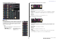
I/O devices and external head amps HA display RMio64-D display This shows the HA settings of the I/O device. Press this area to open the I/O DEVICE HA window, in which you can make detailed head amp settings. Displays the RMio64-D panel. You can press the buttons to change settings. 1 0 2 3 4 5 9 8 A If you press the [SEL] key of an input channel, the corresponding port will light. (It does not light for external CL series consoles.) 8 Analog GAIN knob 9 Indicates the analog gain setting.
I/O devices and external head amps 5 MADI STATUS INPUT status RSio64-D display MADI STATUS OUTPUT status Display information regarding the MADI input and output signals (frame frequency/ number of channels). 1 2 3 45 6 C 6 WORD CLOCK WCLK IN indicator WORD CLOCK MADI indicator WORD CLOCK DANTE indicator WORD CLOCK WCLK IN/MADI/DANTE buttons Used to select the word clock source. WCLK IN Uses the word clock signal being input from the WORD CLOCK IN connector on the rear panel of RMio64-D.
I/O devices and external head amps 3 SLOT 1 - 4 LOCK indicators 7 WORD CLOCK select button This indicates the word clock status for slots 1 to 4. If the word clock is operating normally, this indicator will be green. Off Green (On) LOCK Used to select the word clock source for the RSio64-D. • WORD CLOCK WCLK IN indicator • WORD CLOCK SLOT1 1/2 indicator • WORD CLOCK DANTE indicator Indicates the word clock source status for the RSio64-D. There is no card in the slot.
I/O devices and external head amps 9 USER PATTERN button Third-party equipment’s HA control function Press this button to open the window for setting the audio routing user pattern in the RSio64-D. Patch to the desired output ports of the slots and Dante. It is possible to control supported third-party equipment’s head amps (HA) from the console. You can control HA by registering supported devices in the DANTE SETUP window.
I/O devices and external head amps I/O DEVICE HA window NOTE The indicator on the right side of the rack indicates the control status of the device. Displayed when you press the rack in which the I/O device on the head amp side is mounted. In this window, you can remotely control the head amp of the I/O device from the CL series console by using the on-screen knobs and buttons or the multifunction knobs.
I/O devices and external head amps 6 Displayed port switch tabs Remotely controlling an amp These tabs switch the port that is displayed in the I/O DEVICE HA window. This section explains how to remotely control an amp unit that’s connected to the Dante connector. 7 GC ALL ON button/GC ALL OFF button Switch Gain Compensation on or off for all input channels simultaneously. 8 GC indicator STEP 1. Press the AMP tab in the upper part of the I/O DEVICE screen. 2.
I/O devices and external head amps 3 DANTE SETUP button 1 Display switch buttons Press this button to open the DANTE SETUP window, in which you can make settings for the audio network. Press one of these buttons to view the corresponding I/O device. If you press and hold down this button, all LEDs of the corresponding I/O device will blink. For more information about VIRTUAL/CONFLICT/DUPLICATE displayed below this button, refer to 1 on P.173, “I/O device list.
I/O devices and external head amps 4 Channel name (receiver) NOTE When control on the receiver side is possible, the parameter values for the receiver are sent to the console. Indicates the channel name that is set on the receiver. 5 Frequency Indicates the frequency that is currently set for the RF signal. I/O DEVICE EDIT screen 6 RX.LEVEL/RX.GAIN This screen is displayed when you select the desired wireless device in the I/O DEVICE screen (WIRELESS page). Here you can set the channel name and HA.
I/O devices and external head amps 3 TX.GAIN knob/TX.ATT knob B Mode indicator Sets the gain value for the transmitter. To adjust the value, touch the screen, then press the knob to select it, and use the multifunction knobs. The knob will not display when the wireless device is not support this control. Indicates the mode status of the device such as Diversity mode or Quadversity mode. When not activated, it shows “Diversity mode: off” or “Quadversity mode: off” respectively. 4 TX.
I/O devices and external head amps Example: Connecting the output of a Shure AXT400 to OMNI 1 on a CL console, and assigning the signal to input channel 1. Press the PORT ASSIGN button to open the PORT SELECT window. Select the port to which the output from the AXT400 is connected (OMNI 1). Access the GAIN/PATCH window. Press the INPUT PORT button, and on the PORT SELECT window select the port to which the output signal from the AXT400 is connected (OMNI 1).
I/O devices and external head amps Using an external head amp This assigns the output signal from the AXT400 to the input channel, and at the same time allows you to control and monitor the level of the AXT400 from the input channel.
I/O devices and external head amps Connecting the CL series console to an SB168-ES CL5 Audio signal To remotely control the SB168-ES from the CL series console, install an MY16-ES64 EtherSound card in Slot 1 of the CL, then use an Ethernet cable to connect the CL to the SB168-ES. This connection enables you to remotely control the SB168-ES from the CL series console.
I/O devices and external head amps Ring connection Remotely controlling an external head amp An external head amp ( “external HA” ) connected via MY16-ES64 or NAI48-ES can be remotely controlled from the CL series console. For details on how to connect a CL series console with an external head amp, refer to “Using an external head amp” (page 187) and the external head amp’s operating manual. CL5 Audio signal Remote signal MY16ES64 MY16EX STEP 1. Connect the CL series console to an external HA. 2.
I/O devices and external head amps 5 VIEW switch buttons VIRTUAL RACK screen (EXTERNAL HA page) 5 Switch the virtual rack display between SB168-ES and AD8HR. Select the view that’s appropriate for the connected device. 6 6 COMM PORT switch buttons Specify whether the external HA connected to the slot will be controlled remotely. Select “SLOT1” if you want to remotely control the external HA. EXTERNAL HA PORT SELECT window Select the input port for the external head amp.
I/O devices and external head amps Remotely controlling an external HA from the input channels on a CL series console EXTERNAL HA window Remotely control the external head amp. Display this window by pressing the virtual rack in the I/O DEVICE screen (EXTERNAL HA page). You will be able to use the external HA in the same way as the head amp on an I/O device or on the CL console. For details on the GAIN/PATCH window, refer to “HA (head amp) settings” (page 32). 1 STEP 1.
MIDI MIDI NOTE As the port used for transmission and reception of MIDI messages, you can select either the rear panel MIDI IN/OUT connectors or an I/O card installed in slot 1. All of the functionality described in this section will be available on the port you select. This chapter explains how to transmit MIDI messages from an external device to the CL series console to control the CL console’s parameters, and how to send out MIDI messages from the CL console as you operate the unit.
MIDI 3 PROGRAM CHANGE MODE field MIDI/GPI screen (MIDI SETUP page) Enables you to select the Program Change transmit/receive mode. • SINGLE.............. If this button is on, Program Changes will be transmitted and received on a single MIDI channel (Single mode). • MULTI ................ If this button is on, program changes will be transmitted/received on multiple MIDI channels (Multi mode). • OMNI..................
MIDI MIDI SETUP window (for port selection) MIDI SETUP window (for channel selection) Here you can select the port that will be used to transmit and receive MIDI messages. This window appears when you press the port select button for transmission (Tx) or reception (Rx) in the PORT/CH field. This parameter row enables you to specify MIDI Channels for MIDI message transmission and reception. This window appears when you press the channel select button in the PORT/ CH field.
MIDI Using program changes to recall scenes and library items 1 The CL series console lets you assign a specific event (scene recall or effect library recall) to each Program Change number, so that when this event is executed on the CL console, a Program Change message of the corresponding number will be transmitted to an external device. Conversely, the corresponding event can be executed when a Program Change message is received from an external device. STEP 1.
MIDI 4 Scroll knob • Single mode (when the SINGLE button is on): Only Program Changes of the transmit (Tx) and receive (Rx) channels specified in the MIDI SETUP page will be transmitted and received. When a program change on the Rx channel is received, the event assigned to that program number of the corresponding channel in the list will be executed.
MIDI 2 DESTINATION field STEP 1. Connect the CL series console to an external device. 2. As described in “Basic MIDI settings” (page 192), select the ports and MIDI channels that will be used to transmit/receive control changes. 3. Press the CONTROL CHANGE tab in the MIDI/GPI screen. 4. Switch Control Change transmission/reception on or off, select transmission/ reception mode, and set echo output. 5.
MIDI MIDI/GPI screen (CONTROL CHANGE page) NOTE The channel on which Control Changes are transmitted and received is specified by the PORT/ CH field on the MIDI SETUP page (page 193). You can specify how Control Changes will be transmitted and received, and specify the event (fader/knob operation, [ON] key on/off operation, etc.) assigned to each control number. 3 List 1 Shows the event (fader/knob operation, [ON] key on/off operation, etc.) assigned to each control number. • NO.......................
MIDI Using parameter changes to control parameters MIDI CONTROL CHANGE window Display this window by pressing any event in the CONTROL CHANGE page. In this window, you can specify the event assigned to each control number. On the CL series console, you can use a type of system exclusive messages called “Parameter Changes” to control specific events (fader/knob operations, [ON] key on/off operations, system and user settings, etc.) as an alternative to using Control Changes or NRPN messages.
Recorder Recorder Assigning channels to the input/output of the recorder This chapter explains the functionality and operation of the recorder. Follow the steps below to patch the desired channels to the input and output of the USB memory recorder. You can patch any desired output channel or the direct output of an INPUT channel to the recorder input, and you can patch the recorder output to any desired input channel.
Recorder RECORDER screen (when selecting the USB tab) 6 PLAYBACK OUTPUT GAIN knob In this screen you can assign signals to the input and output of the USB memory recorder, and perform recording and playback operations. 7 PLAYBACK OUTPUT CUE button Sets the level of the signal output to the recorder. Press this button to monitor the signal output from the recorder. NOTE You cannot turn on this button and the RECORDER INPUT CUE button simultaneously. The cue monitoring does not support CUE B.
Recorder RECORDER screen (when selecting the USB tab) NOTE In the case of the CL3/CL1, channels that do not exist on those models will not be shown. Recording audio to a USB flash drive You can record the signal of the desired output channels as an audio file (MP3) onto the USB flash drive inserted in the USB connector located to the right of the display. STEP 1. Refer to “Assigning channels to the input/output of the recorder” (page 200) to assign channels to the input/output of the recorder. 2.
Recorder 5 REC RATE button Directory structure of a USB flash drive Switches the recording rate. You can choose 96 kbps, 128 kbps, or 192 kbps. Higher bit rates will improve the audio quality, but will increase the size of the data. When you connect a USB flash drive to the USB connector, a YPE folder and a SONGS folder within that YPE folder will be created automatically in the root directory of the USB flash drive.
Recorder Playing back audio files from a USB flash drive RECORDER screen 35 You can play back audio files that have been saved on your USB flash drive. In addition to files that were recorded on the CL series console, you can also play files that were copied from your computer to the USB flash drive. The three types of file format that can be played are MP3 (MPEG-1 Audio Layer-3), WMA (Windows Media Audio), and AAC (MPEG-4 AAC). The playable sampling rates are 44.1 kHz and 48 kHz.
Recorder 4 Sub-directory C REPEAT button Indicates each song’s track number, the name of upper level directory, and whether a sub-directory exists (in the case that the directory has been selected). • Upper level............Press this to move up to the directory that is one level higher than the current one.
Recorder Recording or playing back using a computer DAW RECORDER screen (when selecting the USB tab) 3 4 1 If you plan to add DAW software, such as Steinberg Nuendo, to an audio network that includes a CL console and I/O devices, you must use Dante Virtual Soundcard (DVS) driver software. DVS works as an audio interface, making it possible to transmit signals between a DAW and an audio network (that includes a CL series console and I/O devices).
Recorder Word clock settings Setting up Dante Virtual Soundcard In a Dante network, the master device supplies accurate word clock to other devices on the network. If the master device is removed from the network or breaks down, another device will automatically take over as the clock master. To make this setting, in the Function Access Area, press the SETUP button, then the WORD CLOCK/SLOT SETUP button to access the WORD CLOCK/SLOT SETUP window. Install Dante Virtual Soundcard (DVS) and V3.
Recorder Setting up Dante Controller Setting up DAW software Connect the network port of the computer to a GbE-compatible network switch. Configure the computer to obtain an IP address automatically (this is the default setting). You must make the following settings for Dante Controller. • For multi-track recording, patch audio signals from the I/O device to DVS or the Dante Accelerator card.
Recorder Using the CL console with Nuendo Live RECORDER screen (when selecting the Nuendo Live tab) The CL series consoles can operate in an integrated manner with Steinberg’s Nuendo Live DAW software. The “Yamaha Console Extension” software which integrates the CL series and Nuendo Live can be installed in your computer, allowing you to operate Nuendo Live from the CL series console to easily perform multi-track recording operations. Here we explain how to operate Nuendo Live from the CL series console.
Recorder Transport field Specifying DVS or Dante Accelerator Here you can operate the transport of Nuendo Live. Before you proceed, use DANTE SETUP to specify the I/O devices that will be mounted. For details, refer to “Mounting an I/O device on the Dante audio network” (page 263). 7 GO TO PROJECT START button Returns the location to the start of the project. STEP 1. In the Nuendo Live screen, press the NUENDO Live SETUP button. 2.
Recorder 1 Setup method select buttons When setup method selection button = SPECIFIED IP ADDRESS Choose one of the following methods by which to specify DVS or Dante Accelerator. • NO ASSIGN ........................ Not assigned • DVS ..................................... Select a DVS from the device list • SPECIFIED IP ADDRESS .. When using Dante Accelerator, specify the IP address of the computer When using Dante Accelerator, specify the IP address of the computer in the SPECIFIED IP ADDRESS field.
Recorder NOTE • Depending on the firmware version, Dante Accelerator might not support redundant networking. Refer to the following website to check whether your version of the Dante Accelerator firmware supports redundant networking. https://www.yamaha.com/proaudio/ Playing a multi-track project STEP 1. Press the DANTE INPUT PATCH button in the RECORDER screen (Nuendo Live page). 2.
Setup Setup 4 PASSWORD CHANGE button About the SETUP screen 5 SAVE KEY button Press this button to open the PASSWORD CHANGE window, in which you can change the password. Press this button to open the SAVE KEY window, in which you can overwrite (save) the user authentication key (page 220). The SETUP screen enables you to set various parameters that apply to the entire CL console. To access the SETUP screen, press the SETUP button in the Function Access Area. The screen contains the following items.
Setup BUS SETUP field This field enables you to make bus-related settings. D BUS SETUP button Press this button to open the BUS SETUP window, in which you can make MIX bus/ MATRIX bus-related settings. E SURROUND SETUP button Press this button to call up the SURROUND SETUP screen. In this screen, you can switch the bus settings from Stereo mode to Surround mode. If set to Stereo mode, the bus settings for MIX1-6 will be grayed out. If you press the 5.
Setup CONSOLE LOCK button If you set Surround mode, the BUS SETUP screen appears as shown below. This button executes the Console Lock function. If the console password has been set, pressing this button will open the AUTHORIZATION window. Enter the correct password to execute Console Lock. If the console password has not been set, pressing this button will execute Console Lock immediately. CONTRAST/BRIGHTNESS field This field enables you to set the LCD brightness and contrast.
Setup User types and user authentication keys Setting the Administrator password There are three types of user, as follows. To operate the CL series console, you must log-in as a user. • Administrator.... The administrator of the CL console can use all of its functionality. Only one set of Administrator settings is internally maintained in the console. The Administrator can create user authentication keys for other users. • Guest......
Setup CREATE USER KEY window STEP 1. To create a user authentication key on a USB flash drive, connect a USB flash drive to the USB connector. 2. In the Function Access Area, press the SETUP button. 3. In the SETUP screen, press the CREATE USER KEY button. 4. In the CREATE USER KEY window, when you have specified the user name, comment, password, power user privileges on/off, and user rights, press the CREATE button. 5.
Setup Logging-in as Guest Logging-in To operate the CL series console, you must log in as the Administrator, Guest, or a User. User settings for the Administrator and Guest are saved in the console itself. However, to log in as a User you must either select a key that is saved in the console itself, or connect the USB flash drive in which a user authentication key has been saved.
Setup NOTE SETUP screen • If no password has been set, you will simply be logged-in in step 6 when you press the LOAD button. • If the password was incorrect, a message of “WRONG PASSWORD” will appear near the bottom of the screen. • If you have selected a user authentication key that was created on a different CL series console, a keyboard window will appear, allowing you to enter the Administrator password of the CL series console that you will be using.
Setup Editing a user authentication key Changing the user level If you are logged-in as a user, you can edit your USER DEFINED keys, preference settings, comments and password, and save them onto your user authentication key. If you are loggedin as a Power User, you can also change the user level. You can view or change the user level. • Administrator................The Administrator does not have a user level setting, but can change the user level setting of the Guest account. • Guest..................
Setup USER SETUP window (USER LEVEL page) • WITH SEND........................ Restricts operation of that channel’s send parameters. (From MIX, From MATRIX) • DCA MASTER .................... Restricts operation of that channel’s DCA group fader, ON/OFF, and ICON/COLOR/NAME. • DCA GROUP ASSIGN........ Restricts changes of assignment to that DCA group. • SET BY SEL .......................
Setup 5 FILE LOAD Preferences Specifies the types of file that can be loaded from USB flash drives. The user authentication key contains the user level, USER DEFINED keys, and Preference settings. Other data is saved in an “ALL” file. The “ALL” file also includes the USER SETUP settings of the Administrator and the Guest.
Setup • STORE CONFIRMATION • RECALL CONFIRMATION If these ON buttons are lit, a confirmation message will appear when you perform a Store or Recall operation respectively. • [FADER BANK][SEL] LINK Specifies whether channel selection will be linked with fader bank selection. You can set this parameter separately for INPUT (input channels), OUTPUT (output channels), and CUSTOM (Custom fader bank).
Setup USER DEFINED keys • NAME DISPLAY Specifies the content of the name display in the Channel Strip section. When the NAME ONLY button is lit, the channel name and the channel number appear. Select GR METER to display the GR meter and fader level value. Select ENCODER INFO to display the information of a function that has been assigned to the GAIN/PAN/ASSIGN knob on the channel fader strip. This option is the same as the FULL FUNCTION option in CL version 1.7 or earlier.
Setup NOTE • The 16 buttons in the USER DEFINED KEYS page correspond to USER DEFINED keys [1]-[16] on the top panel. The name of the function or parameter assigned to each key appears to the right of the corresponding button. If nothing is assigned to the button, an indication of “---” is shown. • The list shown in the USER DEFINED KEY SETUP window is the same for all models of the CL series.
Setup Functions that can be assigned to USER DEFINED keys FUNCTION NO ASSIGN PARAMETER 1 PARAMETER 2 - No assignment. LATCH - Toggle ALTERNATE FUNCTION each time it is pressed. It goes OFF when the bank is switched. UNLATCH - Switch to ALTERNATE FUNCTION only while pressed. It goes OFF when the bank is switched. group a OVERRIDE ON - Apply a fade-in to the channels in group a where the override button is on, until the level drops to 0 dB (the unity gain).
Setup FUNCTION PARAMETER 1 PARAMETER 2 Description FUNCTION PARAMETER 1 B2 {CL3/CL1} B3 {CL1} GROUP/LINK B4 {CL1} C1 {CL5} CUSTOM FADER BANK C2 {CL5} CHANNEL LINK SCENE MEMORY SCENE C4 {CL5} C5 {CL5} FADE TIME FOCUS RECALL EFFECT RACK 1-8 - - PREMIUM RACK 1A - PREMIUM RACK 1B - EFFECT BYPASS INPUT EQ LIBRARY : - OUTPUT EQ LIBRARY PREMIUM RACK 8A - EFFECT LIBRARY PREMIUM RACK 8B - GEQ LIBRARY INPUT CH LIBRARY FADER BANK SNAPSHOT OUTPUT CH LIBRARY - - LATCH - Toggle the f
Setup FUNCTION PARAMETER 1 PARAMETER 2 Description - Turns the meter’s peak hold function on/off. Lit when ON. SURROUND METER - For Surround mode, toggle between the content to be shown in meters displayed in the Function Access Area. The lamp is off for MIX 16, and on for SURROUND MONITOR. PROGRAM CHANGE PGM 1-128 CONTROL CHANGE CC 1-31, 33-95, 102-119 Transmit the corresponding MIDI message. NOTE ON C-2 (0) For NOTE ON, it goes OFF when the bank is switched.
Setup FUNCTION PARAMETER 1 TRANSPORT RECORDER PARAMETER 2 Recorder transport functions. AUTO REC Shortcut function for STOP REC PLAY. Recording will be initiated in a single action. If this is executed during recording, the file being recorded will first be closed, and then recording will continue with a new file. REC & START Start recording immediately without entering record-ready mode.
Setup FUNCTION PARAMETER 1 PARAMETER 2 *3) DIRECT ASSIGN WITH ON *3) The operations performed when this key is pressed are as follows. - Assignments other than for the channel selected in list 3) are removed. - If a channel is assigned and TALKBACK is ON at the same time, TALKBACK is turned OFF and the channel assignment is removed. - Otherwise, TALKBACK will be ON and the channel assignment will be ON. At this time, the LED display is as shown below.
Setup USER DEFINED knobs NOTE • If you are logged-in as the Administrator, you can also turn on the FOR GUEST button to access the USER DEFINED KNOBS and ASSIGNABLE ENCODER for Guest page and make USER DEFINED knob settings for the Guest account. • The 4 knobs in the USER DEFINED KNOBS and ASSIGNABLE ENCODER page correspond to USER DEFINED knobs [1]-[4] on the top panel. The name of the function or parameter assigned to each knob appears to the right of the corresponding button.
Setup Functions that can be assigned to USER DEFINED knobs Function PARAMETER 1 Function PARAMETER 1 LOW Q LOW FREQUENCY PARAMETER 2 NO ASSIGN - - LOW GAIN AUTOMIXER WEIGHT *1) LOW MID Q LAMP - PANEL - BRIGHTNESS CUE - CH COLOR - HIGH MID FREQUENCY NAME - HIGH MID GAIN A HIGH Q B HIGH FREQUENCY DCA TRIM HIGH GAIN A EXTERNAL HA GAIN1-GAIN8 *10) A HPF FREQUENCY *4) B I/O DEVICE GAIN1-GAIN32 *11) CUE LEVEL - INPUT DELAY DELAY TIME *3) LEVEL *14) INPUT GAIN TH
Setup Function RECORDER PARAMETER 1 PARAMETER 2 INPUT GAIN - OUTPUT GAIN - SCENE SELECT - TO MIX LEVEL MIX1-MIX24 *3) TO MATRIX LEVEL MTRX1-MTRX8 *7) TO MIX PAN MIX1/2-MIX23/24 *3) TO MATRIX PAN MATRIX1/2-MATRIX7/8 *7) TO ST/MONO TOUCH AND TURN PAN/BAL CSR - *5) - *1) SELECTED CH, Automixer ch1-16 *2) SELECTED CH, CL5: CH1-CH72, CL3: CH1-CH64, CL1: CH1-CH48, ST IN 1-ST IN 8, MIX1-MIX24, MTRX1MTRX8, STEREO, MONO (C) *3) SELECTED CH, CL5: CH1-CH72, CL3: CH1-CH64, CL1: CH1-CH48, ST IN
Setup Assignable encoders • The CL3 and CL1 have only one [GAIN/PAN/ASSIGN] key, so the function of all GAIN/PAN/ASSIGN knobs will change simultaneously. On the CL5, you can switch the knob function in block A (left side) and block C/Master fader section (right side) independently by using the corresponding [GAIN/ PAN/ASSIGN] keys. • This assignment does not apply to the multifunction knobs in the Centralogic section, since these knobs are used to control on-screen parameters.
Setup Functions that can be assigned to the assignable encoders PAN GAIN ASSIGN O Function PAN/BALANCE HPF FREQUENCY HPF *4 DYNAMICS1 THRESHOLD THRE1 *5 PAN O DYNAMICS2 THRESHOLD THRE2 *6 BAL O DIGITAL GAIN D.GAIN O EQ ATT ATT A.GAIN *1 D.GAIN *1 MTRX8 PARAMETER 2 O PARAMETER 2 DIGITAL GAIN SELECTED SEND PARAMETER 1 O PARAMETER 1 ANALOG GAIN O Function ASSIGN MATRIX8 SEND O NO ASSIGN GAIN O O O PAN *3 Units of scale are m, ms, ft, and fr.
Setup GAIN/PAN/ASSIGN knob (assignable encoder) functions Custom fader bank Groups that organize channels routed to the top-panel faders are called “fader banks.” There are input and output channel banks, as well as custom fader banks. Custom fader banks enable you to select various combinations of channels, regardless of channel types. This section explains how to set up a custom fader bank. In CL V1.7 and later, the following functions have been added to SENDS ON FADER mode. STEP 1.
Setup 4 Fader select button USER SETUP screen (CUSTOM FADER BANK/MASTER FADER page) Selects the target fader. Press this button to select it, then press [SEL] keys on the top panel to add the corresponding channels to the selected fader bank. 5 Fader assign select button Opens the Fader assign select window, in which you can change the channel assigned to the fader. 1 6 CLEAR ALL button 3 Clears all the current fader bank assignment. Pressing this button will open a confirmation dialog box.
Setup Custom fader bank functions Console Lock Custom fader bank settings can be stored/recalled for individual scenes. Custom fader bank settings are stored in scene data in separate regions for each model. You can temporarily prohibit console operations in order to prevent unwanted operation. This setting disables operations of the panel, so that controllers cannot be operated by an accidental touch or by an unauthorized third party while the operator is taking a break.
Setup Saving and loading setup data to and from a USB flash drive Locking the console STEP 1. In the Function Access Area, press the SETUP button. 2. In the SETUP screen, press the CONSOLE LOCK button. 3. If you are logged-in as a user for whom a password is set, enter the password for the user. 4. Press the OK button to enable Console Lock function.
Setup SAVE/LOAD window The file list contains the following items. When you press an item name, it will turn orange, and the list will be sorted by that item. Each time you press the item name, the sorting order will alternate between ascending and descending order. • FILE NAME................. Indicates the file name or directory name, and shows an icon indicating its type. • COMMENT ................. The comment added to the CL console setting file is displayed here.
Setup C WITH DANTE SETUP AND I/O RACK button 1 TYPE field If this is off, the DANTE SETUP and I/O device settings as well as word clock settings will be omitted when a settings file is loaded. Specifies the types of data to be saved. The view of the TYPE field will vary depending on the tab you select. • ALL tab This button selects all the items. NOTE The DANTE SETUP settings SECONDARY PORT and CONSOLE ID will not be changed even if the “WITH DANTE SETUP AND I/O RACK” button is on.
Setup Loading a file from a USB flash drive • SETUP tab The following table lists the items that you can select. Button Follow the steps below to load a CL settings file (extension .CLF) from the USB flash drive into the CL series console. You can use the same procedure to load the following files as well as settings files. Data content MIXER SETUP Mixer setup OUTPUT PORT Output port MONITOR CUE/MONITOR/OSCILLATOR/TALKBACK .CLF ALL CL console internal setting file MIDI SETUP MIDI setup .
Setup LOAD SELECT screen • EFFECT/GEQ tab The following table lists the items that you can select. Button EFFECT LIB 1 Data content Effect library GEQ LIB GEQ library 8PEQ LIB 8Band PEQ library • PREMIUM tab The following table lists the items that you can select.
Setup Editing the files saved on the USB flash drive • ADMIN tab The following table lists the items that you can select. Type Follow the steps below to perform editing operations such as sorting the files and directories on the USB flash drive, editing the file names or comments, copying, and pasting.
Setup Copying and pasting a file Formatting a USB flash drive Follow the steps below to copy a desired file into buffer memory, and then paste it with a different file name. Follow the steps below to format a USB flash drive. A USB flash drive with a capacity of 4GB or larger will be formatted in FAT32, and a USB flash drive with a capacity of 2GB or smaller will be formatted in FAT16. STEP 1.
Setup Word clock and slot settings Recovering after overcurrent at the USB port Even if the connection with the USB device was stopped because an overcurrent condition occurred at the USB port, it is possible to use the USB device again without turning the console power off and back on. “Word clock” refers to the clock that provides the basis of timing for digital audio signal processing. To send and receive digital audio signals between devices, those devices must be synchronized to the same word clock.
Setup WORD CLOCK/SLOT SETUP window • DANTE 48 k • DANTE 44.1 k The word clock supplied from the Dante jack on the rear panel of the console will be used as the clock source. 4 1 NOTE With CL V2.03 and later, if you initialize the console to factory settings, the default value for the word clock is set to DANTE 48k. This allows you to synchronize word clock even when using multiple CL and QL consoles at their default settings.
Setup Using cascade connections • UNKNOWN (black) This indicates that the clock status cannot be detected because no external device is connected or because there is no valid clock input. You will be able to select this connector/slot, but successful synchronization cannot occur until a valid connection is established. Using multiple CL series consoles, or a CL console and an external mixing console (such as a Yamaha PM5D) in a cascade connection enables buses to be shared among the devices.
Setup CASCADE window (CASCADE OUT PATCH page) NOTE • In Surround mode, you cannot use cascade output on MIX buses1-6. In addition, if you have selected 5.1 SOLO in CUE mode, you cannot monitor CUE from the cascade slave at the cascade master. • If you are making a cascade connection between the CL unit and the PM5D, you can use the CL unit as the cascade slave by setting the PM5D’s CASCADE IN PORT SELECT to a slot. However, only the audio signals will be cascaded, and the control signals cannot be linked.
Setup PORT SELECT window • DCA 9 - 16 cue • DCA 9 - 16 DCA MUTE TARGET (DCA group mute targets) Press the OUT PATCH button to open this window. NOTE Even if the cue mode is LAST CUE, the cue for the target DCA will come on at the same time for consoles linked by cascade connections. • MUTE MASTER Links ON/OFF for mute masters. NOTE The settings of Dimmer function are not linked. Make these settings individually on each console. 2 • SENDS ON FADER Links SENDS ON FADER behavior.
Setup CASCADE window (CASCADE IN ATT page) Operations on the cascade master CL unit STEP 1. In the Function Access Area, press the SETUP button. 2. In the SYSTEM SETUP field of the SETUP screen, press the CASCADE button. 3. In the CASCADE window, press the CASCADE IN PATCH tab. 4. In the CASCADE IN PATCH page, press the IN PATCH button for the bus to which you want to assign the port. 5.
Setup Basic settings for MIX buses and MATRIX buses BUS SETUP window You can make various settings for MIX buses and MATRIX buses. Follow the steps below to change the basic settings for MIX buses and MATRIX buses, such as switching between stereo and monaural, and selecting the send point from which the signal of an input channel will be sent. The settings you make in the following procedure are saved as part of the scene. 1 2 4 1 3 4 STEP 1. In the Function Access Area, press the SETUP button.
Setup 4 PAN LINK button Specifying the brightness of the touch screen, LEDs, channel name displays, and lamps This button appears if SIGNAL TYPE is set to STEREO and VARI is set. If the button is on, the pan setting of signals sent from input channels to the corresponding two buses will link with the STEREO bus pan setting. Follow the steps below to specify the brightness of the touch screen, top panel LEDs, channel name displays, and lamps connected to the rear panel LAMP connectors.
Setup 5 SCREEN 3 FORMAT (Display format) This knob adjusts the brightness of the touch screen. If you have set the brightness to lower than level 2, the CL will start up next time with a brightness setting of 2 so that you will be able to see the screen. Specifies the format in which the date and time of the internal clock are displayed. You can select from the following display formats.
Setup NETWORK window (FOR MIXER CONTROL page) NETWORK window (FOR DEVICE CONTROL page) Use this window to set the console’s IP address, in order to use the NETWORK connector on the rear panel to remote-control the console from CL Editor, StageMix, or the MonitorMix application. Set the UNIT Name and PIN for the MonitorMix application here. For the IP SETTING MODE select buttons, only STATIC IP button is enabled. The other buttons cannot be selected.
Setup NEXT IP SETTING field Dante audio network settings 2 IP SETTING MODE select buttons You will use the CL series console to make Dante audio network settings for the console itself and the I/O devices connected to the Dante connector of the CL series console. This section explains how to make Dante audio network settings. Use these buttons to select how to set the IP address the next time the console is turned on. Select DHCP, AUTO IP, or STATIC IP. NOTE STEP 1.
Setup 2 CONSOLE ID select buttons DANTE SETUP window (SETUP page) Set the IDs for the CL series consoles. If five or more CL units are connected to a network, and you plan not to assign IDs to some of the units, press the OFF button of each of those units to turn off the ID. When the CONSOLE ID select button is set to OFF in the DANTE SETUP screen, the NOT CTRL indicator appears below the Display switch button of each device.
Setup Dante Device Lock • 32bit................... This is effective when transmitting and receiving 25-bit or larger data (when using cascade or gain compensation), but the amount of data being transmitted will increase 20-30% compared to 24-bit. Dante Device Lock prevents changes to the Dante audio network settings of a Dante device by another computer on the same network. Dante Device Lock settings are configured in Dante Controller.
Setup Support for Dante Domain Manager If a device connected to the console is online, and Dante Device Lock is enabled for that device, the LOCKED indicator will appear in each window as shown below. When a DDM server exists in the network, or when enrolling a domain, the DANTE DOMAIN MANAGER field is shown at the top of the DANTE SETUP screen. 1 If Dante Device Lock is enabled for the console, the following specifications will apply.
Setup 3 REMOTE Switching the CONSOLE ID and SECONDARY PORT Displays the access status of the Dante settings of the external Dante devices. • Operator: Editing is available • Guest: Reading is available, editing is disabled • None: Reading and editing are disabled STEP 1. In the DANTE SETUP window (SETUP page), select the CONSOLE ID and the SECONDARY PORT. 2. Press the APPLY button. 3. In the window to confirm the change, press the OK button. The display changes depending on the REMOTE settings.
Setup Connection examples and latency settings • When the CONSOLE ID is set to OFF, the DANTE PATCH BY field is fixed to “DANTE CONTROLLER.” Also, patching cannot be changed in the DANTE INPUT PATCH window. • When the CONSOLE ID is set to OFF, all the mounted devices will be “virtual.” You can edit HA GAIN and other settings for R series units, but notification of the settings will not be sent to the device. This is the same as when the devices are not connected.
Setup Redundant connections Simple 64-in/48-out Daisy chain connections 256-ch HA remote (maximum size) 9 3 8 3 4 7 6 4 5 4 1 2 2 3 2 4 hops = 0.5 ms 1 1 Redundant connections FOH and monitor consoles are sharing 64-in/48-out. 9 hops = 1.0 ms 4 hops = 0.5 ms 3 4 1 2 4 hops = 0.
Setup Mounting an I/O device on the Dante audio network Redundant connections Two CL series consoles are sharing 256-ch HA remote (maximum size) Here’s how to select which of the multiple I/O devices on the Dante audio network will be mounted so that they can be used. Up to 24 units can be mounted for one CL series console. With V4.1 or later, the Shure AXT400, QLXD4, and ULXD4 wireless systems, which do not feature Dante output, can now be controlled.
Setup DANTE SETUP window (DEVICE MOUNT page) 1 DANTE SETUP window 2 1 1 Setup method select buttons Choose one of the following methods for mounting the I/O device. • NO ASSIGN ........................ Not mounted • DEVICE LIST ...................... Select and mount from the device list • SUPPORTED DEVICE ....... Select and mount a supported device • DVS..................................... Enter a device label and mount (only for DVS) • MANUAL.............................
Setup When the setup method select button is DEVICE LIST When the setup method select button is SUPPORTED DEVICE To mount by choosing from a list of the I/O devices on the Dante audio network, press the DEVICE LIST button to display the DEVICE LIST field. If you want to select and mount an I/O device that is supported by the CL series, press the SUPPORTED DEVICE button to see the SUPPORTED DEVICE field. These settings can be made even when not connected to a Dante audio network.
Setup 4 UNIT ID knob When the setup method select button is DVS or MANUAL Use the corresponding multifunction knobs to specify the UNIT ID. The indicator shows the UNIT ID. If you want to enter the device label of an I/O device and mount it, press the DVS or MANUAL button to access the DVS/MANUAL field. NOTE • If there is one I/O device, set the I/O device’s UNIT ID to “1.” • If multiple devices are connected, assign the ID numbers so that there is no conflict between devices.
Setup 3 HA device select buttons REMOTE HA settings Press one of these buttons to open the REMOTE HA SELECT window. The upper line of the button shows the device label. The lower line of the button shows the model name and the number of inputs and outputs. If no device has been mounted, the upper row will indicate “---” and the lower row will show nothing. For more information on VIRTUAL/CONFLICT/DUPLICATE shown below these buttons, refer to 1 on P.173, “I/O device list.
Setup Displaying the device status R-series You can use the touch screen to verify the status of a connected CL series or R-series unit (except the Ro8-D) or the Dante status. In order to verify the status of an R-series unit from the console, it must be assigned to REMOTE HA in DANTE SETUP. The I/O field of the I/O DEVICE screen shows indicators for the status of the R-series units and the Dante network. For firmware that predates support for V1.
Setup Error messages [SYSTEM] indicators The SYSTEM indicators will remain lit/blinking cyclically as follows until the problem has been resolved. If service is necessary, please contact the Yamaha service center listed in the CL5/CL3/CL1 Owner’s Manual. [SYSTEM] indicators Meaning The device has failed. Contact your Yamaha dealer for repair. [SYNC] indicators UNIT ID is not unique.
Setup Information messages If the green indicator is blinking, the unit is operating as the word clock master. If the green indicator lights, the unit is operating as a word clock slave and synching to the word clock. [SYNC] indicators Meaning The indicators will remain lit /blinking cyclically to report the status. If the orange [SYNC] indicator is not lit, the unit is operating correctly. If the green [SYNC] indicator is not lit, the device’s word clock is not defined.
Setup Using GPI (General Purpose Interface) NOTE • With latched operation, the function will switch between active and inactive each time a trigger is input from the external switch. In this case, we recommend that you use a non-locking type of external switch. • With unlatched operation, the function will be active only while the signal from the external switch is at the high level or low level.
Setup 3 GPI IN SETUP button Using GPI OUT The button shows the name of the currently-selected function or parameter. Press this button to display the GPI IN SETUP window. The GPI OUT ports of the GPI OUT connector allow you to control an external device by performing operations on the CL series console. STEP 1. Connect an external device to the CL series console’s GPI connector. 2. In the Function Access Area, press the SETUP button. 3. In the SETUP screen, press the MIDI/GPI button. 4.
Setup 3 GPI OUT SETUP button MIDI/GPI screen (GPI page) 4 The button shows the name of the currently-selected function or parameter. Press this button to display the GPI OUT SETUP window. 3 2 1 You can assign the following functions.
Setup Using FADER START MIDI/GPI screen (FADER START page) Make FADER START settings if you want a device connected to a GPI OUT port to operate in tandem with fader operations. 1 STEP 1. Connect an external device to the CL series console’s GPI connector. 2. In the Function Access Area, press the SETUP button. 3. In the SETUP screen, press the MIDI/GPI button. 4. In the MIDI/GPI screen, press the FADER START tab. 5.
Setup THRESHOLD field The following illustration shows how the signal that is output from the GPI PORT will change in each fader mode when a fader is operated. In this example, UPSTROKE in the THRESHOLD field is set to -60.00, and DOWNSTROKE is set to -∞. (This illustration shows the case in which is selected as the polarity of the GPI OUT port. If the polarity is , the polarity of the output signal will be reversed.
Help function Help function NOTE By default, the character code set of the text file will be detected as UTF-8. However, by adding a line consisting of [ISO-8859-1] or [Shift_JIS] at the beginning of the file, you can force recognition of the file using that character code set. You can specify the desired character code set when using your text editor to save the text file. The Help function is able to display the following text files (character code sets /languages).
Help function Directly recalling the Help for a specific panel controller Using USER DEFINED keys to recall Help directly While holding down the USER DEFINED key to which you have assigned the Help function, press (or rotate) the panel controller for which you want to recall Help. If the explanation is available for the controller, the help for the corresponding item will appear. To close the window, once again press the USER DEFINED key to which the Help function is assigned.
Other functions Other functions NOTE • Do not press any buttons until initialization is complete. • Once initialization is complete, you can continue operation by selecting a different menu instead of pressing the EXIT button. This chapter explains various functions of CL series consoles that are not covered in other chapters.
Other functions Adjusting the faders (Calibration function) NOTE • Faders for which a problem was detected at start-up will already be selected in step 3. • If the RESTART button appears, calibration has failed. Press the RESTART button to execute calibration once again. • Once initialization is complete, you can continue operation by selecting a different menu instead of pressing the EXIT button.
Other functions • INPUT PORT TRIM (Fine adjustment of the analog input gain) Access the INPUT PORT TRIM window, and make fine adjustments to the gain of the specified analog input port in 0.1 dB steps. • SLOT OUTPUT TRIM (Fine adjustment of the slot output port gain) Access the SLOT OUTPUT TRIM window, and make fine adjustments to the gain of the output ports of the specified slot in 0.01 dB steps.
Other functions Adjusting the channel color (Calibration function) Adjusting the brightness of the channel name display If necessary, you can adjust the channel colors. Adjust the channel colors one by one. If necessary, you can adjust the brightness of the channel name display. STEP 1. While holding down the SCENE MEMORY [STORE] key on the panel, turn on the power to the CL unit. 2. On the startup menu screen, press the LED COLOR CALIBRATION button. 3.
Other functions Adjusting the contrast of the channel name display Initializing the console settings and Dante audio network settings If necessary, you can adjust the contrast of the channel name display. It is possible for Dante-related settings to be initialized to their factory-set state when an error occurs on the Dante audio network. STEP 1.
Other functions Update procedure for NAME SUB CPU firmware Update function to Dante firmware If the following window is displayed, the console has entered the mode for updating the NAME SUB CPU firmware. For details about this operation, refer to the “CL5/CL3/CL1 Firmware Update Guide”. Do not power-off the console while the update is proceeding. To exit this mode, press the CANCEL button. If the following window is displayed, the console has entered the mode for updating the Dante module firmware.
Warning/Error Messages Warning/Error Messages Message Message Meaning Meaning DANTE is working at Secondary. The Dante audio network is working on a secondary port. DANTE module Error! An error has occurred in a Dante module. DANTE switched to secondary port. Only the SECONDARY PORT is used, even though a CL series console is being used via a redundant connection. DCA ROLL-OUT : DCA members scrolling. In DCA ROLL-OUT mode, the content is scrolled left to right in the block.
Warning/Error Messages Message Internal Power Supply is Cut Off! Meaning Message The internal (INT) power supply has stopped operating. Alternatively, some other problem has occurred. Please contact your Yamaha service center listed at the end of the Owner’s Manual (separate document). Meaning Please wait, Dante patch is proceeding now. You attempted to edit in the DANTE PATCH screen at a time when patching was not possible.
Warning/Error Messages Message Meaning Message Meaning STEREO Mode : Cannot Use This Function. You cannot use this function in Stereo mode. USB Memory Full! Recorder Stopped. Recorder processing was halted because the USB flash drive capacity ran out while the USB memory recorder was operating. STEREO MODE ON. The console has switched to Stereo mode. USB Memory is Protected! The USB flash drive’s Protect setting is turned on.
Index Index Numerics 8BandPEQ .................................................. 148 A Assignable encoders ................................... 234 Audio file (links to a scene recall)................ 110 AUTOMIXER ............................................... 151 B BUS SETUP window ................................... 252 C Calibration ................................... 278, 279, 281 Cascade connections .................................. 248 Centralogic section........................................
Table of Contents Data List EQ Library List....................................................................... 2 DYNAMICS Library List ......................................................... 3 Dynamics Parameters............................................................ 5 Effect Type List....................................................................... 7 Effects Parameters................................................................. 8 Premium Rack Processor Parameters ...................
EQ Library List # • Libraries created by the user also include type parameters and BYPASS parameters (ON/OFF) for each band. • The type parameter for all read-only presets is “LEGACY (TYPE1).” # 01 Bass Drum 1 02 Bass Drum 2 03 Snare Drum 1 04 Snare Drum 2 05 Tom-tom 1 06 Cymbal 07 High Hat 08 Percussion 09 E. Bass 1 10 E. Bass 2 LOW L-MID H-MID HIGH PEAKING PEAKING PEAKING H.SHELF G +3.5 dB -3.5 dB 0.0 dB +4.0 dB F 100 Hz 265 Hz 1.06 kHz 5.30 kHz Q 1.25 10.0 0.
# 32 Total EQ 3 33 Bass Drum 3 34 Snare Drum 3 37 Piano Low 39 Fine-EQ Cass HIGH PEAKING PEAKING H.SHELF +0.5 dB +2.0 dB +4.0 dB F 67.0 Hz 850 Hz 1.90 kHz 15.0 kHz Q - 0.28 0.70 PEAKING PEAKING PEAKING PEAKING G +3.5 dB -10.0 dB +3.5 dB 0.0 dB F 118 Hz 315 Hz 4.25 kHz 20.0 kHz Q 2.0 10.0 0.40 0.40 PEAKING L.SHELF PEAKING PEAKING G 0.0 dB +2.0 dB +3.5 dB 0.0 dB F 224 Hz 560 Hz 4.25 kHz 4.00 kHz - 4.5 2.8 0.10 L.SHELF PEAKING PEAKING H.SHELF G -9.
# Title Type 18 E. B. Slap COMPRESSOR 19 Syn. Bass COMPRESSOR 20 Piano1 COMPRESSOR 21 Piano2 COMPRESSOR 22 E. Guitar COMPRESSOR 23 A.
DUCKING Dynamics Parameters Ducking is commonly used for voice-over applications in which the background music level is reduced automatically when an announcer speaks. When the KEY IN source signal level exceeds the specified THRESHOLD, the output level is attenuated by a specified amount (RANGE). Dynamics Parameters are the following types.
COMPRESSOR EXPANDER The COMP processor attenuates signals above a specified THRESHOLD by a specified RATIO. The COMP processor can also be used as a limiter, which, with a RATIO of ∞:1, reduces the level to the threshold. This means that the limiter's output level never actually exceeds the threshold. An expander attenuates signals below a specified THRESHOLD by a specified RATIO. Parameter THRESHOLD (dB) Range Parameter Description This determines the level at which compression is applied.
COMPANDER HARD (COMPANDER-H), COMPANDER SOFT (COMPANDER-S) Effect Type List Output Level The hard and soft companders combine the effects of the compressor, expander and limiter. THRESHOLD WIDTH 0dB Input Level The companders function differently at the following levels: 1 0 dB and higher ..................................Functions as a limiter. 2 Exceeding the threshold ....................Functions as a compressor. 3 Below the threshold and width ..........Functions as an expander.
Title Type Delay+Rev DELAY+REV Delay and reverb in parallel Effects Parameters Description DelayRev DELAYREV Delay and reverb in series REV-X HALL, REV-X ROOM, REV-X PLATE DistDelay DISTDELAY Distortion and delay in series Multi Filter MULTI FILTER 3-band parallel filter (24 dB/octave) Freeze FREEZE Simple sampler Distortion DISTORTION Distortion Newly-developed two input, two output reverb algorithm.
STEREO REVERB GATE REVERB, REVERSE GATE Two input, two output stereo reverb. One input, two output early reflections with gate, and early reflections with reverse gate. Parameter Range Description Parameter Range 0.3-99.0 s Reverb time TYPE REV TYPE Hall, Room, Stage, Plate Reverb type ROOMSIZE 0.1-20.0 INI. DLY 0.0-100.0 ms Initial delay before reverb begins LIVENESS 0-10 Early reflections decay characteristics (0 = dead, 10 = live) HI. RATIO 0.1-1.
MOD. DELAY ECHO One input, two output basic repeat delay with modulation. Two input, two output stereo delay with crossed feedback loop. Parameter Range Description Parameter Range Description DELAY 0.0-2725.0 ms Delay time DELAY L 0.0-1350.0 ms Left channel delay time FB. GAIN -99 to +99% Feedback gain DELAY R 0.0-1350.0 ms Right channel delay time HI. RATIO 0.1-1.0 High-frequency feedback ratio FB.DLY L 0.0-1350.0 ms Left channel feedback delay time FREQ. 0.05-40.
FLANGE PHASER Two input, two output flange effect. Two input, two output 16-stage phaser. Parameter Range FREQ. 0.05-40.00 Hz DEPTH MOD. DLY Description Parameter Range Description Modulation speed FREQ. 0.05-40.00 Hz Modulation speed 0-100% Modulation depth DEPTH 0-100% Modulation depth 0.0-500.0 ms Modulation delay time FB. GAIN -99 to +99% Feedback gain (plus values for normal-phase feedback, minus values for reverse-phase feedback) FB.
DYNA.PHASER DUAL PITCH Two input, two output dynamically controlled phaser. Two input, two output pitch shifter. Parameter Range Description SOURCE INPUT, MIDI Control source: input signal or MIDI Note On velocity SENSE 0-100 Sensitivity DIR.
AUTOPAN RING MOD. Two input, two output autopanner. Two input, two output ring modulator. Parameter FREQ. Range 0.05-40.00 Hz Description Parameter Range Modulation speed SOURCE OSC, SELF Description Modulation source: oscillator or input signal DEPTH 0-100% Modulation depth OSC FREQ 0.0-5000.0 Hz Oscillator frequency DIR. *1 Panning direction FM FREQ. 0.05-40.
REV+CHORUS REV+FLANGE One input, two output reverb and chorus effects in parallel. One input, two output reverb and flanger effects in parallel. Parameter Range Description Parameter Range Description REV TIME 0.3-99.0 s Reverb time REV TIME 0.3-99.0 s Reverb time INI. DLY 0.0-500.0 ms Initial delay before reverb begins INI. DLY 0.0-500.0 ms Initial delay before reverb begins HI. RATIO 0.1-1.0 High-frequency reverb time ratio HI. RATIO 0.1-1.
REV+SYMPHO. REVPAN One input, two output reverb and symphonic effects in parallel. This is a 1-in/2-out series-connected reverb and auto-pan effect. Parameter Range Parameter Description Range Description REV TIME 0.3-99.0 s Reverb time REV TIME 0.3-99.0 s Reverb time INI. DLY 0.0-500.0 ms Initial delay before reverb begins INI. DLY 0.0-500.0 ms Initial delay before reverb begins HI. RATIO 0.1-1.0 High-frequency reverb time ratio HI. RATIO 0.1-1.
DELAYER. Parameter One input, two output delay and early reflections effects in series. NOTE L *1 Used in conjunction with TEMPO to determine left channel DELAY NOTE R *1 Used in conjunction with TEMPO to determine right channel DELAY NOTE FB *1 Used in conjunction with TEMPO to determine feedback DELAY Parameter Range Description Range Description DELAY L 0.0-1000.0 ms Left channel delay time DELAY R 0.0-1000.0 ms Right channel delay time FB. DLY 0.0-1000.
DISTDELAY FREEZE One input, two output distortion and delay effects in series. One input, two output basic sampler. Parameter Range Description DST TYPE DST1, DST2, OVD1, OVD2, CRUNCH Distortion type (DST = distortion, OVD = overdrive) DRIVE 0-100 Distortion drive MASTER 0-100 Master volume TONE -10 to +10 Tone control N.
AMP SIMULATE COMP276S One input, two output guitar amp simulator. This effect emulates the characteristics of analog compressors that are widely used in recording studios. It produces a thick, strong frame sound suitable for drums and bass. You can link and control the L and R channel parameters.
EQUALIZER601 OPENDECK This effect emulates the characteristics of 70's analog equalizers. Re-creating the distortion of typical analog circuits will add drive to the sound. It emulates the tape compression created by two open reel tape recorders (a recording deck and a playback deck). You can change the sound quality by adjusting various elements, such as the deck type, tape quality, playback speed, etc. Parameter Range Description LO TYPE HPF-2/1, LSH-1/2 Type of EQ1 LO F 16.0 Hz to 20.
Parameter LIM.ATK Range 0-120 ms Premium Rack Processor Parameters Description Attack time of the limiter LIM.REL *1 Release time of the limiter LIM.KNEE 0-5 Knee of the limiter LIM.BYP OFF/ON Bypasses the limiter PRESENCE -10 to +10 Positive (+) values lower the threshold of the high band and raise the threshold of the low band. Negative (-) values do the opposite. If this is set to 0, the high, mid, and low bands will be affected in the same way.
Portico 5045 EQ-1A This models the Primary Source Enhancer made by Rupert Neve Designs. This processor emulates a vintage EQ that's considered a classic example of a passive EQ. Parameter Range Description Parameter Range Description PROCESS ENGAGE OFF, ON Turns the enhancement circuit on/off. Even when this is off, the signal passes through the audio transformer and discrete amp circuit. (LOW) BOOST 0.0 to 10.
Buss Comp 369 Parameter Parameter Range Description Switches the compressor of low mid band on/off LOW MID CUE ON ON, OFF If this is on, the low mid band signal will be sent to the CUE bus for monitoring. HIGH MID GAIN -18.0dB to 12.0dB High mid band gain HIGH MID THRESHOLD -80.0dB to 0.0dB Threshold of high mid band HIGH MID RATIO 1.0:1 to 20.0:1 Ratio of high mid band HIGH MID ATTACK 0.
Automixer Parameters Parameter Group Range Parameters That Can Be Assigned to Control Changes Description a, b, c Channel control field group Mode Parameter 1 Parameter 2 NO ASSIGN — — BALANCE OUTPUT MIX 1-MIX 24 MATRIX 1-MATRIX 8 STEREO L-STEREO R INPUT CH 1-CH 72*1 STIN1L-STIN8R OUTPUT MIX 1-MIX 24 MATRIX 1-MATRIX 8 STEREO L-MONO(C) OUTPUT — CUE MODE — SURROUND CUE MODE — FADER CUE RELEASE ON — Override OFF, ON Turns on/off overriding of the channel control field ChMode man
Mode INPUT ATT Parameter 1 INPUT Parameter 2 Mode LCR ON MIX 1 ON - MIX24 ON THRESHOLD MATRIX 1 ON - MATRIX 8 ON RANGE MIX 1 POINT - MIX 24 POINT HOLD L DECAY/RELEASE H MIX/MATRIX SEND MIX 1 H - MIX24H MATRIX1 H - MATRIX8 H DECAY/RELEASE L MIX 1 L - MIX24L RATIO MATRIX1 L - MATRIX8 L KNEE MIX 1/2 PAN - MIX 23/24 PAN GAIN H MATRIX1/2 PAN - MATRIX7/8 PAN GAIN L MATRIX 1 POINT - MATRIX 8 POINT MATRIX 1 LEVEL H - MATRIX 8 LEVEL H MATRIX 1/2 PAN - MATRIX 7/8 PAN RELEASE H TO STEREO ON CH
Mode Parameter 1 Mode LOW Q BAND4 FREQ LOW FREQ BAND4 Q LOW GAIN BAND5 BYPASS LOW MID Q BAND5 GAIN H LOW MID FREQ BAND5 GAIN L LOW MID GAIN BAND5 FREQ HIGH MID FREQ HIGH MID GAIN BAND6 BYPASS BAND6 GAIN H HIGH Q BAND6 GAIN L HIGH FREQ BAND6 FREQ HIGH GAIN BAND6 Q LOW TYPE BAND7 BYPASS HIGH TYPE BAND7 GAIN H LOW HPF ON BAND7 GAIN L INPUT BAND7 FREQ BAND7 Q CH 1-CH 72*1 STIN1L-STIN8R BAND8 BYPASS A/B LINK BAND8 GAIN H ON PEQ PEQ BAND8 GAIN L BAND1 BYPASS BAND8 FREQ BAN
Mode RECALL SAFE Parameter 1 ON Parameter 2 CH 1-CH 72*1 STIN1L-STIN8R MIX 1-MIX 24 MATRIX 1-MATRIX 8 STEREO L-MONO(C) GEQ RACK 1A-16B EFFECT RACK 1A-8B PREMIUM RACK 1A-8B DCA 1-DCA16 MATRIX 1 POINT - MATRIX 8 POINT MATRIX 1 ON - MATRIX 8 ON STEREO TO MATRIX MATRIX 1 LEVEL H - MATRIX 8 LEVEL H STEREO L-MONO(C) MATRIX 1 LEVEL L - MATRIX 8 LEVEL L MATRIX 1/2 PAN - MATRIX 7/8 PAN SOURCE SELECT 2CH MONITOR ASSIGN DOWNMIX SURROUND SPEAKER SOLO SURROUND MONITOR SURROUND SPEAKER L SURROUND SPEAKER R — S
NRPN Parameter Assignments Parameter INPUT FADER MIX1-20, MATRIX, STEREO LR MIX9 SEND MIX10 SEND MIX11 SEND MIX12 SEND INPUT to MIX9-16 LEVEL MIX13 SEND MIX14 SEND MIX15 SEND MIX16 SEND MATRIX1 SEND MATRIX2 SEND INPUT to MATRIX1 - 4 LEVEL MATRIX3 SEND MATRIX4 SEND MATRIX1 SEND MATRIX2 SEND MATRIX3 SEND MATRIX4 SEND MIX1-20, STEREO LR to MATRIX LEVEL MATRIX5 SEND MATRIX6 SEND MATRIX7 SEND MATRIX8 SEND INPUT ON MIX1-20, MATRIX, STEREO LR MIX9 SEND MIX10 SEND MIX11 SEND MIX12 SEND INPUT to MIX9-16 ON MIX13 SEN
Parameter MIX9/10 INPUT to MIX9/10-15/16 MIX11/12 PAN MIX13/14 MIX15/16 MATRIX1/2 INPUT to MATRIX1/2, 3/4 PAN MATRIX3/4 MATRIX1/2 MATRIX3/4 MIX1-20, STEREO LR to MATRIX PAN MATRIX5/6 MATRIX7/8 MIX1-8 to STEREO PAN MIX TO ST MIX1-20, MATRIX, BALANCE STEREO LR MATRIX1 SEND MATRIX2 SEND MATRIX3 SEND MIX, STEREO LR, MONO MATRIX4 SEND to MATRIX PRE/POST MATRIX5 SEND MATRIX6 SEND MATRIX7 SEND MATRIX8 SEND MATRIX1 SEND MATRIX2 SEND MATRIX3 SEND MATRIX4 SEND MIX21-24, MONO to MATRIX ON MATRIX5 SEND MATRIX6 SEND MAT
Parameter MATRIX1 SEND MATRIX2 SEND MATRIX3 SEND MATRIX4 SEND MIX21-24, MONO to MATRIX LEVEL MATRIX5 SEND MATRIX6 SEND MATRIX7 SEND MATRIX8 SEND ON MIX21-24, MONO MIX1 SEND MIX2 SEND MIX3 SEND MIX4 SEND INPUT1-56, STIN1-4 to MIX1-8 ON MIX5 SEND MIX6 SEND MIX7 SEND MIX8 SEND MATRIX5 SEND MATRIX6 SEND INPUT1-56, STIN1-4 to MATRIX5-8 ON MATRIX7 SEND MATRIX8 SEND MIX9-24 to STEREO ON MIX TO ST INSERT MIX21-24, MONO MIX1 SEND MIX2 SEND MIX3 SEND MIX4 SEND INPUT1-56, STIN1-4 to MIX1-8 PRE/POST MIX5 SEND MIX6 SEND
Parameter EXTERNAL GAIN1 INPUT GAIN 1 EXTERNAL GAIN2 INPUT GAIN 2 EXTERNAL GAIN3 INPUT GAIN 3 EXTERNAL GAIN4 INPUT GAIN 4 EXTERNAL GAIN5 INPUT GAIN 5 EXTERNAL GAIN6 INPUT GAIN 6 EXTERNAL GAIN7 INPUT GAIN 7 EXTERNAL GAIN8 INPUT GAIN 8 EXTERNAL +48V 1 INPUT +48V 1 EXTERNAL +48V 2 INPUT +48V 2 EXTERNAL +48V 3 INPUT +48V 3 EXTERNAL +48V 4 INPUT +48V 4 HA EXTERNAL +48V 5 INPUT +48V 5 EXTERNAL +48V 6 INPUT +48V 6 EXTERNAL +48V 7 INPUT +48V 7 EXTERNAL +48V 8 INPUT +48V 8 EXTERNAL HPF1 INPUT HPF1 EXTERNAL HPF2 INPU
Mixing Parameter Operation Applicability This table indicates which settings affect the behavior of each input channel and output channel parameter. It also indicates whether or not they can be linked as stereo, and whether or not they are relevant to the RECALL SAFE, GLOBAL PASTE, and USER LEVEL settings, and a channel library.
Parameter To Matrix DELAY Stereo*1 RECALL SAFE, FOCUS RECALL, GLOBAL PASTE*8 CHANNEL LINK ALL Parameter Select button Channel Library USER LEVEL On O INPUT MATRIX ON*3 O INPUT MATRIX ON*7 INPUT FADER/ON*4 O Level O INPUT MATRIX SEND*3 O INPUT MATRIX SEND*7 INPUT FADER/ON*4 O Pan/Balance O*11 O INPUT MATRIX SEND*7 INPUT FADER/ON*4 Pre/Post O O INPUT MATRIX SEND *7 ms O*10 INPUT O INPUT DELAY INPUT PROCESSING O ON O INPUT DELAY O INPUT DELAY INPUT PROCESSING O *
MIX Channels Parameters Linked for a stereo pair RECALL SAFE, FOCUS RECALL, GLOBAL PASTE *8, *12 CHANNEL LINK ALL Parameter Select button USER LEVEL Name, Icon, Color O MIX NAME, GLOBAL OUTPUT NAME OUTPUT NAME Output Patch O MIX OUTPUT PATCH, GLOBAL OUTPUT PATCH OUTPUT PATCH Out Patch O MIX INSERT PATCH, GLOBAL OUTPUT PATCH OUTPUT PATCH In Patch O MIX INSERT PATCH, GLOBAL OUTPUT PATCH OUTPUT PATCH +48V, Gain, Gain Compensation O MIX INSERT PATCH, GLOBAL HA MIX PROCESSING Insert1
*9 *11 *12 *13 *14 Applies to ALL only when using GLOBAL PASTE, and only to ON/OFF. Balance only For GLOBAL PASTE, the MIX, MATRIX, STEREO, and MONO settings of each channel will be set in common as the OUTPUT. Linked only for stereo MATRIX Applicable to parameters only when ALL is selected.
*7 *8 *9 *11 *12 *14 Valid when they are set for either the Send source channel or Send destination channel. Settings marked GLOBAL in this table apply to all channels; these settings are GLOBAL RECALL SAFE, FOCUS PARAMETER, and GLOBAL PASTE for PATCH/NAME. Applies to ALL only when using GLOBAL PASTE, and only to ON/OFF. Balance only For GLOBAL PASTE, the MIX, MATRIX, STEREO, and MONO settings of each channel will be set in common as the OUTPUT. Applicable to parameters only when ALL is selected.
DCA Parameters MUTE RECALL SAFE, FOCUS RECALL, GLOBAL PASTE ALL Parameter Select button Parameters USER LEVEL RECALL SAFE ALL Name, Icon, Color O DCA NAME DCA MASTER Name On O DCA LEVEL/ON DCA MASTER On MUTE GROUP MASTER Fader O DCA LEVEL/ON DCA MASTER Dimmer MUTE GROUP MASTER Fade Time, On O *9 STORE MUTE Assign MUTE GROUP ASSIGN Input DCA Assign *9 Applies to ALL only when using GLOBAL PASTE, and only to ON/OFF.
MIDI Data Format DATA This section explains the format of the data that the CL series is able to understand, send, and receive. STATUS DATA 1 CHANNEL MESSAGE If [TABLE] is selected 1.1 NOTE OFF (8n) Reception These messages are echoed to MIDI OUT if [OTHER COMMAND ECHO] is ON. They are received if [Rx CH] matches, and used to control effects. STATUS DATA 1000nnnn 8n Note off message 0nnnnnnn nn Note number 0vvvvvvv vv Velocity (ignored) 1.
2 SYSTEM REALTIME MESSAGE EOX 2.1 SONG SELECT (F3) Reception Select the track number shown in the TITLE LIST screen of the USB memory recorder. STATUS 11110011 F3 Song select Song number 0sssssss ss Song number (0-127) 2.2 TIMING CLOCK STATUS 11111000 F8 Timing clock 2.3 ACTIVE SENSING (FE) Reception Once this message has been received, MIDI communication will be initialized (e.g., Running Status will be cleared) if no message is received for an interval of 400 ms.
In the data portion, seven words of 8-bit data are converted into eight words of 7-bit data. [Conversion from actual data to bulk data] d[0-6]: actual data b[0-7]: bulk data b[0] = 0; for( I=0; I<7; I++){ if( d[I]&0x80){ b[0] |= 1<<(6-I); } b[I+1] = d[I]&0x7F; } [Recovery from bulk data to actual data] d[0-6]: actual data b[0-7]: bulk data for( I=0; I<7; I++){ b[0] <<= 1; d[I] = b[I+1]+(0x80&b[0]); } 3.3 PARAMETER CHANGE Reception This message is echoed if [PARAMETER CHANGE ECHO] is ON.
4.2.
4.4 FUNCTION CALL - LIBRARY ATTRIBUTE - 4.4.2 Format (PARAMETER REQUEST) 4.4.1 Format (PARAMETER CHANGE) Reception The PARAMETER CHANGE will be sent with Device number [Rx CH] immediately the data is received. Reception Data will be received when [PARAMETER CHANGE Rx] is on and the Device number of both [Rx CH] and SUB STATUS match. The data will be echoed when [PARAMETER CHANGE ECHO] is on. When the message is received, the title of the specified memory/library will be edited.
4.5.2 Format (PARAMETER REQUEST) 4.6 FUNCTION CALL - COLLECTION STORE - Reception The PARAMETER CHANGE will be sent with Device number [Rx CH] immediately the data is received. 4.6.1 Format (PARAMETER CHANGE) STATUS ID No.
4.8 FUNCTION CALL - CHANNEL - 4.8.1 Pair ON/OFF Trigger Format (PARAMETER CHANGE) Reception Data will be received when [PARAMETER CHANGE Rx] is on and the Device number of both [Rx CH] and SUB STATUS match. The data will be echoed when [PARAMETER CHANGE ECHO] is on. STATUS ID No.
Input/Output Characteristics Digital input & output characteristics Analog input characteristics Input Terminals OMNI IN 1-8 GAIN For Use With Nominal 7.5kΩ 50-600Ω Mics & 600Ω Lines +66dB -6dB +64dB TALKBACK Input Level Actual Load Impedance 10kΩ +20dB *1 Nominal Max. before clip -82dBu (61.6μV) -62dBu (0.616mV) -42dBu (6.16mV) -10dBu (245mV) +10dBu (2.45V) +30dBu (24.5V) -60dBu (0.775mV) -40dBu (7.75mV) Sensitivity -70dBu 50-600Ω Mics & (0.245mV) 600Ω -26dBu Lines (38.
I/O SLOT (1-3) characteristics Each I/O Slot accepts a mini-YGDAI card. Only Slot1 has a serial interface. Control I/O characteristics Terminal MIDI WORD CLOCK Format Level IN MIDI - OUT MIDI - IN - TTL/75Ω terminated BNC Connector OUT - TTL/75Ω BNC Connector - - IEEE802.3 10BASE-T/100Base-TX - 0V-12V*2 USB 2.
Sampling Frequency Electrical Characteristics Parameter All faders are nominal when measured. Output impedance of signal generator:150ohms Frequency Response. Input OMNI IN 1-8 Fs= 44.1 kHz or 48 kHz @20 Hz-20 kHz, referenced to the nominal output level @1 kHz Output RL OMNI OUT 1-8 600 Ω PHONES Conditions GAIN: +66dB 8Ω Total Harmonic Distortion. Input OMNI IN 1-8 Internal OSC Output 600 Ω OMNI OUT 1-8 600 Ω PHONES 8Ω Typ. Max. -1.5 0.0 0.5 -3.0 0.0 0.
Mixer Basic Parameters Function Parameter Function Decay= 48 kHz: 5 msec to 42.3 sec 44.1 kHz: 6 msec to 46.1 sec Libraries Name Number Releace= 48 kHz: 5 msec to 42.3 sec 44.1 kHz: 6 msec to 46.1 sec Total Scene Memory Preset 1 + User 300 301 Input CH Library Preset 1 + User 199 200 Output CH Library Preset 1 + User 199 Input EQ Library Output EQ Library Dynamics 1 Range= Gate: -∞ dB to 0 dB Ducking: -70 dB to 0 dB Gain= 0.
Pin Assignment 4 9 14 15 20 7 13 19 6 12 18 23 1 2 3 8 11 2 1 5 1 10 16 17 22 3 8 5 21 15 DC POWER INPUT 11 10 9 9 GPI 6 METER (CL3/CL1 only) Pin Signal Name Pin Signal Name Pin Signal Name Pin Signal Name Pin Signal Name Pin Signal Name 1 +24V 13 GND 1 GPO1 9 GPO2 1 RESET 6 +3.3LD 2 +24V 14 GND 2 GPO3 10 GPO4 2 SDA 7 +3.
Note On Note Off Key’s Ch’s Velocity After Touch 49 :True# O: Yes X: No Mode 2: OMNI ON, MONO Mode 4: OMNI OFF, MONO Mode 1: OMNI ON, POLY Mode 3: OMNI OFF, POLY Aux Messages X X X X O O Effect Control Recorder Control Assignable Bank Select Data Entry NRPN LSB,MSB Assignable Cntrl Effect Control Memorized Memorized Remarks *1 Bulk Dump/Request and Parameter Change/Request.
Yamaha Pro Audio global website https://www.yamaha.com/proaudio/ Yamaha Downloads https://download.yamaha.