
User Manual
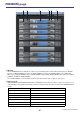
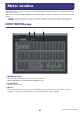
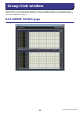
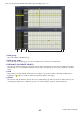

Table Of Contents
- Getting Started
- Main window
- Overview window
- Selected Channel window
- Library window
- Premium Rack Library window
- Patch Editor window
- Virtual Rack window
- Meter window
- Group/Link window
- Scene window
- Custom Fader Bank Setup window
- Custom Fader Bank window
- User Defined Keys Setup window
- User Defined Knobs Setup window
- Sends On Fader window
- Outport Setup window
- Keyboard Shortcuts
- Index

CL Editor Owner’s Manual
86
This window shows the signal levels of each section in the CL, letting you check for the presence of signals and whether an
overload is occurring.
This window is divided into INPUT METER and OUTPUT METER; to switch pages, click the tabs located at the top of the
window.
In order to view the CL’s signal levels in the Meter window, make sure that CL Editor and the CL itself are
synchronized. Also, please make sure that the Level Meter is enabled in the System Setup dialog box.
INPUT METER page
1 METERING POINT
Select one of the following as the point where metering will occur.
PRE G.C, PRE D.GAIN, POST D.GAIN, PRE FADER, POST ON
2 PEAK HOLD
Switches peak hold on/off.
3 Meters
These peak level meters show the input level of each channel. The current fader value is shown in the box below.
If clipping occurs at any one of the detection points in the channel, the Σ segment will light.
Meter window
NOTE
1 2 3