Owner’s Manual Bedienungsanleitung Mode d’emploi Manual de instrucciones EN DE FR ES ZH JA
FCC INFORMATION (U.S.A.) 1. IMPORTANT NOTICE: DO NOT MODIFY THIS UNIT! This product, when installed as indicated in the instructions contained in this manual, meets FCC requirements. Modifications not expressly approved by Yamaha may void your authority, granted by the FCC, to use the product. 2. IMPORTANT: When connecting this product to accessories and/or another product use only high quality shielded cables. Cable/s supplied with this product MUST be used. Follow all installation instructions.
PRECAUTIONS PLEASE READ CAREFULLY BEFORE PROCEEDING * Please keep this manual in a safe place for future reference. WARNING Always follow the basic precautions listed below to avoid the possibility of serious injury or even death from electrical shock, short-circuiting, damages, fire or other hazards. These precautions include, but are not limited to, the following: Power supply/Power cord Water warning • Only use the voltage specified as correct for the device.
Connections Handling caution • Before connecting the device to other devices, turn off the power for all devices. Before turning the power on or off for all devices, set all volume levels to minimum. • When turning on the AC power in your audio system, always turn on the device LAST, to avoid speaker damage. When turning the power off, the device should be turned off FIRST for the same reason. • Use only speaker cables for connecting speakers to the speaker jacks.
Introduction Thank you for your purchase of the YAMAHA T5n, T4n, T3n Series Power Amplifier. This series of power amplifiers was developed from Yamaha’s wealth of experience in building PA equipment and its tradition of careful attention to every detail of circuit design. These power amplifiers feature high power — thanks to EEEngine (Energy Efficient Engine) technology — and superb quality together with superior reliability and stability, guaranteeing the highest possible audio performance.
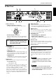
Controls and Functions ■ Front Panel 2 6 5 6 T5n 9 1 43 1 POWER switch and indicator Press to toggle the power on or off. The POWER indicator lights up green when the power is ON. If the amplifier is connected to an amp control device such as the ACD1 or ACU16-C and the amplifier has been commanded to enter STANDBY mode, this indicator will light orange. 2 TEMP indicator Lights up red if the heat sink temperature exceeds 85°C (185°F).
Controls and Functions ■ Rear Panel 2 4 3 51 1 Input connectors 6 8 7 4 DATA PORT jacks • XLR3-31 type input connectors The pins are wired as shown below (IEC 60268). An amp control device, such as the ACD1 or ACU16-C, can be connected to the DATA PORT jack for monitoring or controlling the amplifier from the external device. 5 AMP ID switch Hot Ground Cold • Euroblock input connectors These are balanced input connectors. The included Euroblock connectors can be used to make connections here.
Speaker Connections Speakers can be connected to the amplifier as shown below. Note that actual speaker impedance varies according to the connection method and the number of speakers. Please be sure that your speakers’ impedance is not less than the relevant minimum value indicated below. ■ STEREO Mode Set the MODE switch on the rear panel to “STEREO” to use the unit as a stereo amplifier. The volume controls on the front panel (A and B) let you control the volume of each channel independently.
Speaker Connections Speaker Connections ■ BRIDGE Mode (use as high-power mono amplifier) Set the MODE switch on the rear panel to “BRIDGE” to use the unit as a high-power mono amplifier. The volume control A on the front panel lets you control the volume. ● 5-way binding post ● Speakon connector – + Total speaker impedance: 4 Ω (minimum) Total speaker impedance: 4 Ω (minimum) Wiring Turn off the POWER switch before connecting external devices to the amplifier.
Wiring 1. If the wire insertion ports are closed, turn the screws on top of the connector counterclockwise to open the ports. 2. Insert the wires into the appropriate ports, following the indication of the pole on the input terminal, and turn the screws on top of the connector clockwise to fix the wires. 3. Attach the Euroblock connector to the input terminal on the amplifier. Use a screwdriver to fix the wires. + – G ■ Speaker Connection ● 5-way binding post 1.
Filter Element Cleaning To ensure adequate cooling air intake, the filter elements must be cleaned when they have become clogged. Follow the description below to clean the filter elements. 1. Make sure that the power to the amplifier is turned off. 2. Disconnect the power plug from the AC outlet. 3. Remove the two screws that secure the front filter grilles to the amplifier. 4. Remove the filter elements, and wash them in plain water.
Specifications T5n Output Power 1 kHz THD + N = 1% 120V 230V 240V 8 Ω per channel 1350 W 1350 W 1400 W 4 Ω per channel 2200 W 2350 W 2500 W 2 Ω per channel 2500 W 2500 W 2500 W 8 Ω bridge 4400 W 4700 W 5000 W 5000 W 4 Ω bridge 20 ms burst MIN 5000 W 5000 W 2 Ω per channel 3400 W 3400 W 3600 W 4 Ω bridge 6800 W 6800 W 7200 W STEREO mode: 100 V line, 1250 W/8 Ω BRIDGE mode: 200 V line, 2500 W/16 Ω Constant voltage line Input Sensitivity RL=8 Ω 26 dB position +16.6 dBu +16.
Specifications All Models THD + N 20 Hz-20 kHz, Half power, RL = 4 Ω, 8 Ω MAX Intermodulation Distortion 60 Hz:7 kHz, 4:1, Half power MAX 0.1 % Frequency Response RL = 8 Ω, Po = 1 W 20 Hz-20 kHz MAX 0 dB TYP 0 dB MIN -0.5 dB MIN 67 dB 800 0.1 % Channel Separation Half power, RL = 8 Ω, 1 kHz Att. Max, input 600 Ω shunt Damping Factor RL = 8 Ω, 1 kHz MIN Voltage Gain Att.
1 FG FG J : 100V 50Hz/60Hz U: 120V 60Hz H: 230V 50Hz A: 240V 50Hz CH B – + G – + G 2 EMI FILTER 3 +5V BA GAIN –3.
Dimensions 16.5 4.4 380 426.
Performance Graph +2 FREQUENCY RESPONSE INPUT: Ch A/B (XLR 150 ohm) OUTPUT: Ch A/B (8 ohm) 0 dBr = 1 W ATT: MAX +0 dBr -2 -4 -6 -8 10 20 50 100 200 500 1k 2k 5k 10k 20k 100k Hz Current Draw T5n 8 Ω/ch 4 Ω/ch 2 Ω/ch 8 Ω/ch 4 Ω/ch 2 Ω/ch Line Current (A) 100 V/120 V 230 V/240 V 0.08 0.04 1.0 0.5 10.4 5.7 14.7 8.1 20.0 11.0 20.6 11.3 30.9 17.0 40.6 22.
Yamaha Pro Audio global web site: http://www.yamahaproaudio.com/ Yamaha Manual Library: http://www.yamaha.co.jp/manual/ C.S.G.