
User Manual
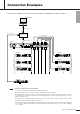

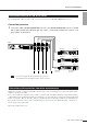


Table Of Contents

ACD1 Owner’s Manual
12
Connection Examples
The ACD1 allows daisy-chain connection of up to 32 PC-N or Tn series units using Ethernet cable via the [DATA PORT] con-
nector.
Connection procedure
1. Make the appropriate AMP ID and terminator settings using the [AMP ID] switches located on the rear
panel of the connected amplifiers.
Specify a different AMP ID for each amplifier that is connected to the same ACD1. The AMP ID will be the total of the
values of the switches that are set to ON.
Set the T (terminator) switch to ON for the last amplifier in the daisy-chain.
2. Use Ethernet cables to daisy-chain the ACD1’s [DATA PORT] connector and the [DATA PORT] connector of
the amplifiers, as shown in the illustration.
It is not necessary to connect the amplifiers in order of their AMP ID, but connecting them in this order will make it easier
to determine the AMP ID without looking at the rear panel.
• The total maximum length of Ethernet cable that can be used is 500 meters.
• Use CAT5 or higher UTP straight Ethernet cable or STP straight Ethernet cable that connects all eight pins.
• Both PC-N series units and Tn series units can be connected to the same ACD1.
•You can make connections to either of the two [DATA PORT] connectors on the amplifier.
Connections with the PC-N or Tn series
In the example shown in this illustration, the AMP ID
is 28 (16+8+4) and the terminator is ON.
AMP ID : 0
T : OFF
AMP ID : 1
T : OFF
AMP ID : 2
T : OFF
AMP ID : 31
(Maximum of
32 amps)
T : ON
DATA PORT connector
DATA PORT
DATA PORT
DATA PORT
ACD1
NOTE