NetworkAmp Manager Owner’s Manual N K R O W T E N A B U H E
Important Information Special Notices • • • • • • • • The software and this owner’s manual are the exclusive copyrights of Yamaha Corporation. Use of the software and this manual is governed by the license agreement which the purchaser fully agrees to upon breaking the seal of the software packaging. (Please read carefully the Software Licensing Agreement at the beginning of the printed ACU16-C/NHB32-C Owner’s Manual before installing the application.
Contents 1 Welcome . . . . . . . . . . . . . . . . . . . . . . . . . . . . . . . . . 4 Introduction . . . . . . . . . . . . . . . . . . . . . . . . . . . . . . . . . . . . . . . . . . . . . . . . . . . . . . . . 4 What is CobraNet? . . . . . . . . . . . . . . . . . . . . . . . . . . . . . . . . . . . . . . . . . . . . . . . . . . . 5 Using Multiple PCs . . . . . . . . . . . . . . . . . . . . . . . . . . . . . . . . . . . . . . . . . . . . . . . . . . . 6 2 Getting Started . . . . . . . . . . . . . . .
Introduction 4 1 Welcome Introduction The Yamaha NetworkAmp Manager software is for controlling and monitoring Yamaha PCxxxxN series power amplifiers, the ACU16-C Amp Control Unit, and the NHB32-C Network Hub and Bridge. It runs on standard Windows PCs and can be connected to an ACU16-C or NHB32-C by using either USB or RS-232C. Multiple ACU16-Cs and NHB32-Cs can be managed from a single PC running NetworkAmp Manager, which can be connected to any ACU16-C or NHB32-C on the CobraNet network.
Welcome What is CobraNet? CobraNet is technology developed by Peak Audio (Cirrus Logic, USA) that transmits uncompressed digital audio signals in realtime over a fast Ethernet cable. It can carry up to 64 channels in each direction or 128 channels total for both directions (64 channels total for both directions in a network that uses a repeater hub). (However, the number of channels is limited by conditions such as the performance of your equipment and on the type of audio signal.
Using Multiple PCs 6 Using Multiple PCs • • • Several PCs running NetworkAmp Manager can be connected to the CobraNet network, offering simultaneous control and monitoring from several locations within a venue. Up to 16 channels of real-time data (e.g., level meter information) can be transmitted across the network simultaneously.
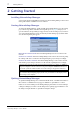
Getting Started 2 Getting Started Installing NetworkAmp Manager System requirements and installation instructions for NetworkAmp Manager can be found in the printed ACU16-C/NHB32-C Owner’s Manual. Starting NetworkAmp Manager To start NetworkAmp Manager, double-click the NetworkAmp Manager icon. If a startup project has been specified on the General Setup dialog box (see page 8), that project is opened. Otherwise, the Open dialog box appears and you can select the project you want to open.
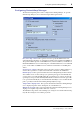
Configuring NetworkAmp Manager 8 Configuring NetworkAmp Manager The General Setup dialog box is used to configure NetworkAmp Manager. To open the General Setup dialog box, choose General Setup from the Option menu. PC I/F for amp control: These options are used to specify the MIDI interface NetworkAmp Manager should use to communicate with the connected ACU16-C/NHB32-C. The options available depends on what MIDI drivers you have installed on your PC.
Getting Started Working with Projects • • • • NetworkAmp Manager setups are stored as projects. Project files have the file name extension “.apj”. To create a new project, choose New from the File menu. To open a previously saved project, choose Open from the File menu. To save the current project, choose Save from the File menu. To save the current project with a new name, choose Save As as from the File menu. Only one project can be open at a time.
Main Window 10 3 Touring NetworkAmp Manager Main Window This is NetworkAmp Manager’s main window. The left pane displays the CobraNet network tree, consisting of ACU16-Cs, NHB32-Cs, and power amps. The right pane displays the various NHB and ACU pages. The name and unit ID of the device currently selected in the network tree are displayed at the top of the right pane. If it’s an ACU16-C, “ACU - name [Unit ID]” is displayed. If it’s an NHB32-C, “NHB - name [Unit ID]” is displayed.
Touring NetworkAmp Manager Menus File New Creates a new project Open Opens an existing project Save Saves the current project Save As Saves the current project with a new name Disconnect from Network1 Disconnects NetworkAmp Manager from the network Connect to Network1 Connects NetworkAmp Manager to the network Connect & send to network Connects NetworkAmp Manager to the network and sends the project settings to all devices on the network Exit Quits NetworkAmp Manager 1.
Network Tree Network Tree The network tree displays all the ACU16-Cs, NHB32-Cs, and power amps in the project in a tree-like structure. Items are displayed in order of unit ID. The tree can be expanded and collapsed by clicking the plus and minus symbols. The following table lists the items that can appear in the network tree.
Touring NetworkAmp Manager PRJ The PRJ icon always appears at the top of the network tree. The following menu appears when you right-click the PRJ icon. Add: Adds an ACU16-C or NHB32-C to the project. When you choose either of these commands, a dialog box appears for you to specify the device name and unit ID. Rename: Opens the Rename dialog box so you can rename the project. ACU When you click an ACU icon, the ACU pages appear in the main window’s right pane.
Network Tree 14 NHB When you click an NHB icon, the NHB pages appear in the main window’s right pane. The following menu appears when you right-click an NHB icon. Delete: Deletes the NHB32-C from the project. A confirmation message appears before the NHB32-C is deleted. Rename: Opens the Rename dialog box so you can rename the NHB. AMP When you click an AMP icon, the ACU Amp pages appear in the main window’s right pane. The following menu appears when you right-click an AMP icon.
NHB Pages 4 NHB Pages This chapter explains the NHB pages, which can be selected while an NHB32-C is selected in the network tree. Devices on a CobraNet network transmit and receive audio data by matching bundle numbers. Matching the bundle number on the transmitting and receiving devices is analogous to making a physical cable connection between two devices.
CobraNet Page 16 intensify the restrictions on Ethernet’s packet delivery times, and therefore reduce the maximum number of switches that can be used. For details, refer to the Peak Audio website (http://www.peakaudio.com). Note: If the latency is 1.33 ms, the number of bundles that can be handled by this single device on a CobraNet network will be limited to a total of four bundles for transmission and reception. When changing the latency to 1.
NHB Pages Patch Page This page is used to assign AES/EBU inputs and outputs to individual CobraNet channels and to store and recall assignment patches. Before making any assignments, you must specify the bundles that contain the CobraNet channels you want to patch (see page 15). EDIT indicator AES/EBU inputs and outputs are assigned to CobraNet channels on two 32 x 32 grids, one for inputs, one for outputs. To make an assignment, click on the grid at the relevant intersection.
Word Clock Page 18 AES/EBU In to CobraNet: This tab is used to assign AES/EBU inputs to CobraNet channels. CobraNet to AES/EBU Out: This tab is used to assign CobraNet channels to AES/EBU outputs. Store/Recall: These buttons are used to store and recall patches. A patch consists of all AES/EBU input and output to CobraNet channel assignments. There are 100 patch memories.
ACU Pages 5 ACU Pages This chapter explains the ACU pages, which can be selected while an ACU16-C is selected in the network tree. Devices on a CobraNet network transmit and receive audio data by matching bundle numbers. Matching the bundle number on the transmitting and receiving devices is analogous to making a physical cable connection between two devices.
Patch Page 20 Note: If two or more latencies exist within a CobraNet network, there is a danger that the devices may become unable to communicate correctly with each other. You must make the same latency setting for all devices in a single network. Note: If you are unable to change the latency, refer to Troubleshooting (see page 38). Patch Page This page is used to assign individual CobraNet channels to ACU16-C analog outputs.
ACU Pages Amp Pages The Amp pages are used to control and monitor power PROTECT indicator amplifiers. There are four Amp pages: Amp 00–07, Amp 08–15, Amp 16–23, and Amp 24–31. Each page can display the channels of up to eight power amplifiers. Power amplifiers can have 2, 4, 6, or 8 channels. The screen shot shown here features two channels of a PC9500N power amplifier. Amp name: This displays the power amplifier’s name. Only the first 21 letters of the name are displayed.
Channel Detail Page 22 Channel Detail Page The Channel Detail page offers a detailed view of each channel. It can be opened by clicking the Channel Detail tab while an ACU16-C is selected in the network tree, or by clicking a power amplifier channel icon in the network tree. PROTECT indicator Channel select: This section is used to select the power amplifier channel that you want to view. Use the Amp pop-up menu to select a power amplifier. Use the CH pop-up menu to select a channel.
ACU Pages Mode indicator: This displays the power amplifier mode for each pair of channels: STEREO, PARALLEL, or BRIDGE. ATT fader: This fader attenuates the channel’s input signal. The numerical value below the fader is the current attenuation setting in dB. Attenuation can also be set by clicking the Up and Down arrow buttons, or by entering a value from the keyboard. Phase button: This button is used to set the channel’s input signal phase: Normal or Reversed.
Threshold Page 24 Threshold Page This page is used to specify the wattage, temperature, and the minimum and maximum load impedance thresholds at which you want NetworkAmp Manager to issue a warning. The thresholds can be set individually for each power amplifier channel. Warnings are displayed in the Log window and recorded in the log file. Amp: This column lists the power amplifiers by ID number and name. CH: This column lists the power amplifier channels.
Other Functions 6 Other Functions Logging Events NetworkAmp Manager compares the threshold values set on the ACU Threshold page (see page 24) with the amp’s operating status and issues a warning if a value is exceeded. Warnings are displayed in the Log window (see page 29) and recorded to the log file. Log files are CSV format text files that can be opened by any text editor, word processor, or spreadsheet. Note: Don’t open the log file while NetworkAmp Manager is running.
Logging Events 26 There are five types of event: Warning, Online/Offline Status, Power Switch, Error, and Network Mode. These are explained below. 1 Warning Event This type of event occurs when a specified threshold is exceeded (see page 24).
Other Functions New ACU16-C detected ACU16-C gone offline New NHB32-C detected NHB32-C gone offline [ACU#xx] [ACU#xx] [NHB#xx] [NHB#xx] Online/Offline Status events appear in blue in the Log window. 3 Power Switch Event This type of event occurs when an amplifier is set to On or Standby. Date, Time, LineKind, Device For example: 01/Aug/2002, 21:30:25, PowerOn, [ACU#00 AMP#00] In other words, amp #00, connected to ACU #00, was turned on at 21:30:25 on 01/Aug/2002.
Logging Events 28 AES/EBU Input Sync Error [NHB#xx AES/EBUx CH7/8] Word Clock Unlocked [NHB#xx] Word Clock Unlocked [ACU#xx] Unexpected data change detected [NHB#xx...] Unexpected data change detected [ACU#xx...] Error events appear highlighted in red in the Log window, as shown below. 5 Network Mode This type of event occurs when COM or MIDI is activated or deactivated.
Other Functions Log Window The Log window opens automatically, if it’s not already, when an event occurs. This window can also be opened by choosing Log Window from the Window menu. Each time an event occurs, the details are displayed in the window, which scrolls automatically.
Locking NetworkAmp Manager 30 Locking NetworkAmp Manager You can lock NetworkAmp Manager to prevent unauthorized operation. Locking NetworkAmp Manager 1 Choose Operation Lock from the Option menu. The Operation Lock dialog box shown below appears. 2 Enter a password in the Password and Confirm fields. 3 Click Lock. NetworkAmp Manager is locked and the Operation Unlock dialog box appears, as shown below.
Other Functions Using COM & MIDI Modes 1 CobraNet’s Serial Bridge feature allows serial data to be transmitted over the network. Normally, the ACU16-C and NHB32-C use the Serial Bridge to transmit amp control data. However, it can be used to transmit MIDI data (Program Change and Control Change) or AD824 head amp control data between any two NHB32-Cs on the network. The Serial Bridge cannot carry Amp Control, MIDI, and AD824 data simultaneously.
Group View 32 Group View With Group View you can view and control groups of channels from any amplifiers on the network. There are eight group pages and up to 16 channels can be displayed on each. To open the Group View page, choose Group View from the View menu. The eight groups are selected by clicking the tabs along the top of the page. The Network tab is used when NetworkAmp Manager is being run on several PCs.
Other Functions Editing Groups 1 Up to 16 channels can be added to each Group View page. Choose Group View from the View menu. The Group View page appears. 2 Right-click on the page and select Edit Group View from the pop-up menu. The Group View Setup dialog box appears, as shown below. 3 Select a group in the Groups list. You can sort groups by using the Move up and Move down buttons. 4 Use the Group name field to edit the group’s name. This is the name that appears on the Group View page tabs.
Group View 34 7 Select a channel in the CH list and click the Add [>] button. The channel is added to the group. To add all channels, click the Add All [>>] button. 8 To remove a channel from the group, select it and then click the Remove [<] button. To remove all channels, click the Remove All [<<] button. You can sort the grouped channels by using the Move up and Move down buttons. 9 When you’ve finished, click the OK button to apply your edits and close the Group View Setup dialog box.
Other Functions Control Link With Control Link you can group power amplifiers for simultaneous control of power Standby and On. Up to 16 Control Link groups are available. To open the Control Link page, choose Control Link from the View menu. The STANDBY and ON buttons are unavailable when no power amplifiers are in a group or when the group is disabled. When a group is enabled, you can click the STANDBY button to simultaneously set all power amplifiers in that group to Standby mode.
Control Link 36 Editing Groups 1 Choose Control Link from the View menu. The Control Link page appears. 2 Right-click on the page and select Edit Control Link from the pop-up menu. The Control Link Setup dialog box appears, as shown below. 3 Select a group in the Groups list. 4 To enable the group, click its check box. The check boxes are used to enable and disable groups. You can sort the groups by using the Move up and Move down buttons. 5 Use the Group name field to enter a name for the group.
Other Functions 9 When you’ve finished, click the OK button to apply your edits and close the Control Link Setup dialog box. If you click the Apply button, your edits are applied and the dialog box remains open. Click Cancel to leave the settings unchanged and close the dialog box.
Appendix 38 Appendix Troubleshooting Symptom Advice The Connect to Network command in the File menu is unavailable? This command is unavailable if no PC interface has been specified. Choose General Setup from the Option menu and specify interfaces for MIDI IN and MIDI OUT. Forgotten the password? Delete the password file located in the folder in which NetworkAmp Manager is installed, make sure that the Password field and the Confirm field are blank, and then click Unlock.
Glossary Glossary This glossary contains terms relevant to NetworkAmp Manager, the ACU16-C, and NHB32-C. A wealth of information about CobraNet, with sections especially for designers and installers, is available on the Peak Audio Web site at http://www.peakaudio.com. If you are designing a network, we strongly recommend that you visit this Web site and study the information available in order to take full advantage of the CobraNet technology. 100Base-T: See Fast Ethernet.
Glossary 40 CobraNet: Developed by Peak Audio, CobraNet technology allows real-time uncompressed digital audio distribution over industry standard 100Base-T Ethernet networks. Up to 128 channels, 64 in each direction, can be carried simultaneously over a switched 100Base-T network (64 channels on repeater networks). CobraNet supports a 48 kHz sampling rate with 16, 20, or 24-bit resolution. CobraNet devices can happily coexist with networked computers, printers, etc.
Glossary Media converter: A device that converts from one type of distribution media to another, for example, Ethernet (100Base-TX) to fiber optic (100Base-FX). Multicast bundle: CobraNet bundles 1 through 255 are multicast bundles, which means they are transmitted to all devices on the network regardless of whether any devices are configured to receive them. Multicast bundles allow point-to-multipoint connections and can be used with repeater hubs or switching hubs.
Glossary 42 Unicast bundle: CobraNet bundles 256~65,279 are unicast bundles. (However since the ACU16-C/NHB32-C support only bundle numbers 0~16,383, they can only use unicast bundles 256~16,383.) In other words, these are transmitted only if the two devices are set to transmit and receive that specific bundle. Unicast bundles only allow point-to-point connections and as such are far more bandwidth efficient than multicast bundles.
Yamaha Manual Library http://www.yamaha.co.jp/manual/english/ M.D.G.