
User Manual


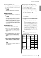

Table Of Contents

Connections and Setting Up
XMV8280/XMV8140/XMV8280-D/XMV8140-D Owner’s Manual
18
The XMV features a switch function between 8Ω and 4Ω to
guarantee the output in case it is connected to a speaker with
an impedance of 8Ω or higher.
If you connect a speaker with an impedance of 8Ω or higher,
set the [SPEAKERS] DIP switches to 8Ω. If you connect a
speaker with an impedance of 4Ω or higher, but lower than
8Ω, set the [SPEAKERS] DIP switches to 4Ω.
When using low impedance connections with
Double Power mode
If you use Double Power mode, input/output will be dis-
abled for channels B, D, F and H.
Depending on the impedance (4Ω or 8Ω) of the connected
speakers, set the [SPEAKERS] DIP switches as follows.
When using high impedance connections
Depending on the specifications (70V or 100V) of the
system in which this unit is being installed, set the
[SPEAKERS] DIP switches as follows.
Connecting Speaker Cables
The [SPEAKERS] output connectors (page 15) on the rear
panel are barrier strip type connectors. We will explain con-
nections using a spade lug and connections using a bare con-
ductor.
If using a spade lug
From below, insert the spade lug all the way, and tighten
the screw.
If using a bare conductor
Wrap the conductor around the barrier strip terminal as
shown below, and tighten the screw. Be sure that the bare
wire does not touch the chassis.
Total impedance(x) Setting
4Ω x 8Ω 4Ω
8Ω x 8Ω
Setting
Switches 1–4
(channels C and G)
Switches 5–8
(channels A and E)
560W{280W}, 8Ω
560W{280W}, 4Ω
NOTE
If you make settings for low impedance connections, the
HPF will automatically be turned OFF.
Setting
Switches 1–4
(channels C, D, G and H)
Switches 5–8
(channels A, B, E and F)
70V
100V
NOTE
When the device is turned on, it will set HPF to 80 Hz, if
the device is set to high impedance connection. If the
device is set to low impedance connection, HPF will be
not set.
CAUTION
Make sure that the power is turned off. If the power is
on, you risk electrical shock.
NOTE
• If the [SPEAKERS] DIP switches (page 15) are in Dou-
ble Power mode (switch 4 or 8 is in the lowered posi-
tion), audio will not be output from the corresponding
channel (channel B, D, F or H).
•Ensure that tension is not applied to the speaker cable.
• Connect the cables so that the amplifier’s “+” and “-”
symbols match those of the speaker. If they are
reversed, the polarity will be reversed.
TIPS
Since a large amount of current can flow in a speaker
cable, a magnetic field will be generated. If sensitive cir-
cuits such as a microphone input cable or a microphone
amp are located near a speaker cable, electromagnetic
induction may produce noise in the input cable or circuit.
Input cables and devices that contain sensitive circuits
should be kept at a distance from speaker cables; we
also recommend that you fasten the cables in place.
>
0.15"
(
>
3.7mm)
<
0.31"
(
<
7.8mm)
=
=
=
=
15mm*
* Actual size Speaker cable
Wire should
not touch
the chassis.