
User Manual
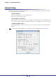

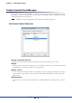
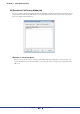
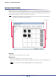

Table Of Contents
- Cover
- What is Amp Editor?
- Special Notices
- Contents
- Preparing for operation
- An overview of Amp Editor
- Setup
- Basic operations in Amp Editor
- Main panel window
- Objects in the window and their function
- Menus in the main panel window
- Preferences
- Event Log
- Device Information
- Scene Manager
- Alert Setup
- Word Clock (TXn only)
- Speaker Processor Library Manager (TXn only)
- Clock
- Language (TXn only)
- GPI (ACD1 only)
- Utility
- IP Address
- IP Control Port No.
- Firmware Update (Updating the internal firmware)
- Scene Link Manager (for devices other than XMV)
- Network Setup
- Synchronization (Synchronization with devices)
- Custom Control Panel Manager
- System View Creator
- Speaker Processor Library Converter
- Tree View window
- Detail View window
- Device Properties window
- Signal Path View window (TXn only)
- Component editor (TXn only)
- Custom control panels
- Appendix

Chapter 5 Main panel window
Amp Editor Owner’s Manual
99
[View Type]
Here you can select the type of template to be placed in the System View (page 28). The following types are
available.
Different Types cannot be combined in a single System View.
[Rows]
This specifies the number of cell rows. You can specify between 1 and 8.
• If you reduce the number of rows, the information for amplifiers assigned to the deleted cells will be
deleted. Rearrange the cells as necessary.
[Colums]
This specifies the number of cell columns. You can specify between 1 and 8.
• If you reduce the number of columns, the information for amplifiers assigned to the deleted cells will
be deleted. Rearrange the cells as necessary.
[Standby/On]
If this is selected, a button that changes the power supply status of all registered amplifiers will be added in
the upper part of the custom control panel.
Type A (For the TXn) Type B (For the TXn)
NOTE
NOTE