
User Manual
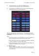
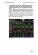
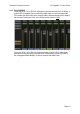
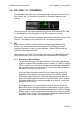
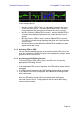
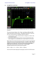
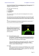
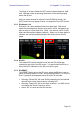
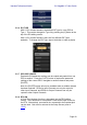
Table Of Contents
- 1.0 System Requirements
- 2.0 Wi-Fi Settings
- 3.0 Getting Started
- 4.0 Mixer Window
- 4.1 Channel Bank Navigation
- 4.2 Layer Navigation
- 4.3 Channel Names and Colors
- 4.4 Faders
- 4.5 Channel ON
- 4.6 CUE
- 4.7 Dual Cue Mode
- 4.8 SOLO Mode
- 4.9 Master Bank
- 4.10 GAIN
- 4.10.1 Digital Gain
- 4.10.2 Gain Compensation Mode
- 4.10.3 Analog Gain / Digital Gain Link
- 4.10.4 ALL GC ON
- 4.10.5 ALL GC OFF
- 4.10.6 Input Port
- 4.10.7 Phantom Power
- 4.10.8 Phase
- 4.10.9 Dante Wireless Microphone Control and Monitoring
- 4.10.10 Non-Dante Wireless Microphone Control and Monitoring
- 4.10.11 Input Port Patching
- 4.10.12 Input Port Patch Options
- 4.10.13 Multi-Channel Input Patching
- 4.11 SENDS ON FADERS
- 4.12 DCA FADERS
- 5.0 EQ / PAN / 5.1 / DYNAMICS
- 6.0 OUTPORTS
- 7.0 UTILITY
- 8.0 RACK
- 8.1 GEQ Racks
- 8.2 EFFECT Rack
- 8.3 EFFECT EDITING
- 8.3.1 Current Effect
- 8.3.2 Effect Type Selection
- 8.3.3 Effect Library
- 8.3.4 Input and Output Patch Assignments
- 8.3.5 Input and Output Meters
- 8.3.6 Effect Bypass
- 8.3.7 Effect Cue
- 8.3.8 Close Effect Editor
- 8.3.9 Parameter Editing using Sliders
- 8.3.10 Numerical Parameter Editing
- 8.3.11 Multi-Segment Buttons
- 8.3.12 Accessing Parameters
- 8.3.13 Additional Parameters
- 8.3.14 Wet/Dry Mix
- 8.4 GRAPHICAL EFFECT EDITING
- 8.4.1 REV-X Time/Level Parameters
- 8.4.2 REV-X Space Parameters
- 8.4.3 REV-X Filter Parameters
- 8.4.4 REVERB Time/Level Parameters
- 8.4.5 REVERB Space Parameters
- 8.4.6 REVERB Filter Parameters
- 8.4.7 REVERB Dynamics Parameters
- 8.4.8 STEREO REVERB Program
- 8.4.9 MONO/STEREO/MOD DELAY Parameters
- 8.4.10 DELAY LCR Parameters
- 8.4.11 ECHO Parameters
- 9.0 SCENE MEMORY
- 10.0 SETUP
- 10.1 Fader Delay
- 10.2 Filled EQ Graph
- 10.3 Enable Inc/Dec Scene Recall
- 10.4 Show Send Levels in Meter Bridge
- 10.5 Enable Phantom Power Switching
- 10.6 Set EQ band to 0dB with Double-Tap
- 10.7 Show dB Markings on Mixer
- 10.8 Set DCA to 0dB with Double-Tap
- 10.9 Disable Screen Auto-Lock
- 10.10 Cue Operation Mode
- 10.11 Cue A Mode
- 10.12 Cue B Mode
- 10.13 Solo in Place Mode
- 10.14 Channel Select – StageMix Follows Console
- 10.15 Channel Select – Console Follows StageMix
- 10.16 Input Meter Point
- 10.17 Output Meter Point
- 10.18 Display Key Input for Dynamics Meters
- 10.19 RTA Peak Hold Mode
- 10.20 RTA Input Gain
- 10.21 RTA Number of Bands
- 11.0 Troubleshooting

Yamaha Professional Audio CL StageMix V7 User Guide
Page 35
5.0 EQ / PAN / 5.1 / DYNAMICS
The thumbnail area at the top of each channel strip displays an EQ curve, the
Pan position, the 5.1 Surround Pan position, or Dynamics status for that
channel.
The buttons to the left of the thumbnails are used to select between EQ, PAN,
5.1 and Dynamics mode by tapping on the left or right cursor button.
Note: the 5.1 option will only be available when Surround Mode is active in the
console. This feature is only relevant for CL V3 firmware and higher.
5.1 EQ
Every channel in the CL series console has a dedicated Parametric EQ
(PEQ). CL series consoles also have Graphic EQs (GEQs) that can be
assigned (inserted) on input or output channels. 8-Band PEQ can also be
used as an alternative to a GEQ.
Note: assignment of GEQs to channels and mounting of 8-Band PEQs in the
GEQ Rack must be done on the console and cannot be done in StageMix.
5.1.1 EQ Curve in Mixer Window
The EQ curve section on the Mixer Window will show the user whether
a GEQ or 8-Band PEQ is available on any channel. If a GEQ or 8-Band
PEQ is available on a channel in addition to the dedicated 4-Band PEQ,
the user will be able to view the curve for any of these EQs and access
the editing screen for any type of EQ.
Green and blue dots below each EQ curve indicate the types of EQ
available on that channel, the insert position for the GEQ or 8-Band
PEQ, and the type of EQ that is currently displayed for that channel. A
green dot indicates PEQ and a blue dot indicates GEQ. When only the
dedicated 4-Band PEQ is currently available on a channel, no dots will
appear below the curve.
Every channel in a CL console has two insert points and GEQs or 8-
Band PEQs can be inserted into either of these points. A blue or green
dot in the middle of the EQ thumbnail area represents a GEQ or 8-Band
PEQ in Insert 1. A blue or green dot on the right side represents a GEQ
or 8-Band PEQ in Insert 2. The green dot for dedicated 4-Band PEQ will
always be on the left side of the thumbnail area.