
User Manual
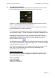
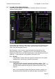
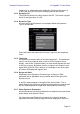
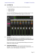
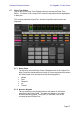
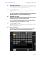
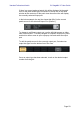
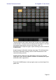
Table Of Contents
- 1.0 System Requirements
- 2.0 Wi-Fi Settings
- 3.0 Getting Started
- 4.0 Mixer Window
- 4.1 Channel Bank Navigation
- 4.2 Layer Navigation
- 4.3 Channel Names and Colors
- 4.4 Faders
- 4.5 Channel ON
- 4.6 CUE
- 4.7 Dual Cue Mode
- 4.8 SOLO Mode
- 4.9 Master Bank
- 4.10 GAIN
- 4.10.1 Digital Gain
- 4.10.2 Gain Compensation Mode
- 4.10.3 Analog Gain / Digital Gain Link
- 4.10.4 ALL GC ON
- 4.10.5 ALL GC OFF
- 4.10.6 Input Port
- 4.10.7 Phantom Power
- 4.10.8 Phase
- 4.10.9 Dante Wireless Microphone Control and Monitoring
- 4.10.10 Non-Dante Wireless Microphone Control and Monitoring
- 4.10.11 Input Port Patching
- 4.10.12 Input Port Patch Options
- 4.10.13 Multi-Channel Input Patching
- 4.11 SENDS ON FADERS
- 4.12 DCA FADERS
- 5.0 EQ / PAN / 5.1 / DYNAMICS
- 6.0 OUTPORTS
- 7.0 UTILITY
- 8.0 RACK
- 8.1 GEQ Racks
- 8.2 EFFECT Rack
- 8.3 EFFECT EDITING
- 8.3.1 Current Effect
- 8.3.2 Effect Type Selection
- 8.3.3 Effect Library
- 8.3.4 Input and Output Patch Assignments
- 8.3.5 Input and Output Meters
- 8.3.6 Effect Bypass
- 8.3.7 Effect Cue
- 8.3.8 Close Effect Editor
- 8.3.9 Parameter Editing using Sliders
- 8.3.10 Numerical Parameter Editing
- 8.3.11 Multi-Segment Buttons
- 8.3.12 Accessing Parameters
- 8.3.13 Additional Parameters
- 8.3.14 Wet/Dry Mix
- 8.4 GRAPHICAL EFFECT EDITING
- 8.4.1 REV-X Time/Level Parameters
- 8.4.2 REV-X Space Parameters
- 8.4.3 REV-X Filter Parameters
- 8.4.4 REVERB Time/Level Parameters
- 8.4.5 REVERB Space Parameters
- 8.4.6 REVERB Filter Parameters
- 8.4.7 REVERB Dynamics Parameters
- 8.4.8 STEREO REVERB Program
- 8.4.9 MONO/STEREO/MOD DELAY Parameters
- 8.4.10 DELAY LCR Parameters
- 8.4.11 ECHO Parameters
- 9.0 SCENE MEMORY
- 10.0 SETUP
- 10.1 Fader Delay
- 10.2 Filled EQ Graph
- 10.3 Enable Inc/Dec Scene Recall
- 10.4 Show Send Levels in Meter Bridge
- 10.5 Enable Phantom Power Switching
- 10.6 Set EQ band to 0dB with Double-Tap
- 10.7 Show dB Markings on Mixer
- 10.8 Set DCA to 0dB with Double-Tap
- 10.9 Disable Screen Auto-Lock
- 10.10 Cue Operation Mode
- 10.11 Cue A Mode
- 10.12 Cue B Mode
- 10.13 Solo in Place Mode
- 10.14 Channel Select – StageMix Follows Console
- 10.15 Channel Select – Console Follows StageMix
- 10.16 Input Meter Point
- 10.17 Output Meter Point
- 10.18 Display Key Input for Dynamics Meters
- 10.19 RTA Peak Hold Mode
- 10.20 RTA Input Gain
- 10.21 RTA Number of Bands
- 11.0 Troubleshooting

Yamaha Professional Audio CL StageMix V7 User Guide
Page 52
5.8 DYNAMICS PROCESSOR EDITING
Tap on any of the Dynamics thumbnails in the Mixer Window to access the
Dynamics Editing screen.
The left side of this screen (Channel Strip) is identical to the EQ Editing screen
with channel fader, On button, Cue button, input and output meters, channel
name, color and navigation buttons.
Both Dynamics 1 and 2 can be viewed and edited simultaneously in the
Dynamics Editing screen. A graphical curve for each dynamics processor
displays the effect of non time-based parameters on the dynamics processor’s
behaviour. A gain reduction meter appears below each curve.
5.8.1 Default
The [DEFAULT] button resets the dynamics parameters to the default
settings for the current type of dynamics processor.
5.8.2 Copy/Paste
The [COPY] button copies the dynamics processor settings. This
includes the type of dynamics processor and its parameter values. The
[PASTE] button pastes the settings to a dynamics processor in any
channel.
Note: it is not possible to paste the dynamics processor settings to a
dynamics processor that does not allow that type of processor to be