Owner’s Manual PRECAUTIONS pages 4 to 6 Quick Start Guide Troubleshooting pages 9 to 11 pages 18 to 20 EN
UL60065_03-C ATTE N TION RISQUE DE CHOC ELECTRIQUE-NE PAS OUVRIR CAUTION: TO REDUCE THE RISK OF ELECTRIC SHOCK, DO NOT REMOVE COVER (OR BACK). NO USER-SERVICEABLE PARTS INSIDE. REFER SERVICING TO QUALIFIED SERVICE PERSONNEL. The above warning is located on the rear of the unit. ATTENTION : POUR RÉDUIRE LES RISQUES D'ÉLECTROCUTION, NE PAS RETIRER LE CAPOT (OU LE DOS). NE CONTIENT PAS DE PIÈCES NÉCESSITANT L'INTERVENTION DE L'UTILISATEUR.
FCC INFORMATION (U.S.A.) 1. IMPORTANT NOTICE: DO NOT MODIFY THIS UNIT! This product, when installed as indicated in the instructions contained in this manual, meets FCC requirements. Modifications not expressly approved by Yamaha may void your authority, granted by the FCC, to use the product. 2. IMPORTANT: When connecting this product to accessories and/or another product use only high quality shielded cables. Cable/s supplied with this product MUST be used. Follow all installation instructions.
PA_en_8 1/2 PRECAUTIONS PLEASE READ CAREFULLY BEFORE PROCEEDING Please keep this manual in a safe place for future reference. WARNING Always follow the basic precautions listed below to avoid the possibility of serious injury or even death from electrical shock, short-circuiting, damages, fire or other hazards.
PA_en_8 1/2 Handling caution • Do not rest your weight on the device or place heavy objects on it. Avoid applying excessive force to the buttons, switches or connectors to prevent injuries. Yamaha cannot be held responsible for damage caused by improper use or modifications to the device, • Avoid pulling the connected cables to prevent injuries or damage to the device.
The model number, serial number, power requirements, etc., may be found on or near the name plate, which is at the bottom of the unit. You should note this serial number in the space provided below and retain this manual as a permanent record of your purchase to aid identification in the event of theft. Model No. Serial No. (bottom_en_01) OBSERVERA! Apparaten kopplas inte ur växelströmskällan (nätet) så länge som den ar ansluten till vägguttaget, även om själva apparaten har stängts av.
Thank you and congratulations on your purchase of the Yamaha MG12XUK mixing console. This product is a mixing console for adjusting the balance of multiple sound sources. This manual explains, for users who may not be familiar with mixers, how to mix multiple sound sources during live performances by a band or in other events. Please read this manual thoroughly to get the most out of the product and ensure long-term, trouble-free use. After reading this manual, please keep it available for future reference.
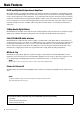
Main Features D-PRE and High-Quality Operational Amplifiers Mono input channels are equipped with “D-PRE” Class-A discrete microphone preamplifiers. The D-PRE head amplifier features an inverted Darlington circuit used in high-end audio devices. This circuit uses multi-stage amplifying elements to ensure high current and low impedance, for an audio texture with crispness and richness in the low and mid frequencies.
Quick Start Guide STEP 1 Connecting external devices, such as speakers, microphones and instruments 1. 2. Make sure that all devices to be connected to the unit are turned off. Connect speakers, microphones and instruments referring to the connection example below.
Quick Start Guide STEP 2 Getting sound to the speakers 1. 2. Make sure that the [ panel is set to the [ / ] switch at the rear ] position (power off). 5. Set the equalizer knobs (green) to the center “” position. Connect the supplied AC adaptor. 4 q Connect the power adaptor with the gap of the [GAIN] plug facing up, aligning it to the [AC ADAPTOR IN] connector.
Quick Start Guide 8. Turn on the power to the connected devices in the NOTE following order: The volume can be adjusted by using three functions; [PAD], [GAIN], and [LEVEL]. Once you set the [PAD] switch and the [GAIN] knob, avoid adjusting those controls as much as possible. Instead normally use the [LEVEL] knob to adjust the volume. For details about each function, see the “Controls and Functions” section. ment), (microphone), (audio device) [ (instru- / ] (this unit) (speakers).
Controls and Functions e [HPF] (High-Pass Filter) switches Top panel Channel section (Input: q to !4) Turning the switch on ( ) will apply a high-pass filter that attenuates frequencies below 80 Hz. When speaking into the microphone, you may want to turn this switch on ( ), in order to reduce unwanted vibration and wind sound received by the microphone. r [GAIN] knobs Determines the basic volume for each of the channels 1 to 6.
Controls and Functions [BAL]: Determines the volume balance of the stereo channels (7/8 to 11/12) (L/R) sent to the stereo bus. When the knob is located at the 12 o’clock position, the sound of the stereo channels will be sent to the stereo bus channels (L and R) at the same volume respectively. [PAN/BAL]: Provides both [PAN] and [BAL] functions.
Controls and Functions Top panel Master section (Output: !5 to @3) !8 [MONITOR OUT] jacks For connecting a monitor system for operators. These jacks support phone plugs. !9 [POWER] LED Lights when the [ / ] switch on the rear panel is set to on (pressed to the [ ] position). @0 Level meter The L and R meters show the level (volume) of the signal output from the [STEREO OUT] jacks by seven steps; “PEAK” (+17), “+10”, “+6”, “0”, “-6”, “-10”, and “-20” dB.
Controls and Functions Top panel Internal effect section (Output: q to u) e [PARAMETER] knob Adjusts the parameter (depth, speed, etc.) for the selected effect. The last value used with each effect program is saved. For details about the parameter, see the “Effect Programs” list on page 17. NOTE When you change to a different effect program, the unit automatically restores the value that was previously used with that program (regardless of the current position of the [PARAMETER] knob).
Controls and Functions Rear panel not plan to use the unit for a while, be sure to unplug the AC adaptor from the outlet. USB section (@4 to @6) @6 [USB 2.0] terminal For connecting to a computer via a commercially available USB 2.0 cable. (This product does not come with a cable.) The sound of the stereo bus is output to the computer. (The [STEREO LEVEL] knob @3 does not affect the sound.) For inputs and outputs to/from the computer, you may need a dedicated USB driver.
Applying Effects The MG12XUK features high-quality built-in signal processing effects that are in the same league as our famed SPX effect processor series. Applying effects (as described below) allows you to simulate the acoustics of different performance environments. Effect Programs No.
Troubleshooting When No Sound Is Output Refer to this section when no sound is output or the volume is very low. This information is for when sound is output from the [STEREO OUT] jacks or the [PHONES] jack. For details about these functions, see “Controls and Functions” on pages 12 – 16. STEP 1 Connections and Signal Flow Check if the instruments, microphones, and speakers are connected correctly, and if any of the cables are damaged. When connecting guitars or basses to the MG, use DI boxes.
Troubleshooting STEP 2 Setting Switches and Controls Check the overall balance Use the settings shown in the illustration to check the overall balance from speakers or headphones. [PHANTOM +48V] switch Turn this switch on (the indicator lit) when using a condenser microphone. [GAIN] knobs Turn until the [PEAK] indicator begins to flash intermittently. • To prevent an unwanted burst of noise from the speakers, turn off powered speakers (or power amps) before turning on the [PHANTOM +48V] switch.
Troubleshooting Other The power does not come on. Is the mixer connected to an independent power source (generator, etc.) or a power strip with switches? Check that the power of that device is turned on. No sound is output. Are external instruments (including microphones) and speakers connected correctly? Are your cables shorted? Are the [GAIN] knobs for each channel, [LEVEL] knobs, [STEREO LEVEL] knob adjusted to appropriate levels? Are the[LINE The sound is low, distorted, or noisy.
Technical Specifications General Specifications 0 dBu = 0.775 Vrms, Output impedance of signal generator (Rs) = 150Ω All level controls are nominal if not specified. Frequency Response Input to STEREO OUT +0.5 dB/-1.0 dB (20 Hz to 48 kHz) , refer to the nominal output level @ 1 kHz, GAIN knob: Min Total harmonic distortion (THD+N) Input to STEREO OUT 0.02 % @ +14dBu (20 Hz to 20kHz), GAIN knob: Min 0.
Technical Specifications Analog Input Characteristics 0 dBu = 0.775 Vrms Input Terminals PAD 26 dB GAIN Trim Position Actual Load Impedance Input Level For Use with Nominal +64 dB OFF +20 dB MIC/LINE 1-6 3kΩ +38 dB 50–600Ω Mics/Lines ON -6 dB LINE 7/8, 9/10 Sensitivity *1 Nominal Max. before clip -72 dBu (0.195 mV) -60 dBu (0.775 mV) -40 dBu (7.75 mV) -28 dBu (30.9 mV) -16 dBu (122.8 mV) +4 dBu (1.228 V) -46 dBu (3.884 mV) -34 dBu (15.46 mV) -14 dBu (154.6 mV) -2 dBu (615.
Technical Specifications Jack and Connector List Jacks and Connectors Polarities Configurations INPUT MIC/LINE, STEREO OUT OUTPUT Pin 1: Ground Pin 2: Hot (+) Pin 3: Cold (–) XLR Jack MIC/LINE*, AUX SEND, MONITOR OUT, STEREO OUT Tip: Hot (+) Ring: Cold (–) Sleeve: Ground PHONES Tip: L Ring: R Sleeve: Ground LINE (stereo input channels) Tip: Hot Sleeve: Ground Ring Sleeve Tip TRS Phone Connector Sleeve Tip TS Phone Connector These jacks also can be connected with TS phone connectors.
MG12XUK Owner’s Manual INPUT 1 to 4 (L) (L/MONO) +30dBu +20dBu +10dBu 0dBu -10dBu -20dBu -30dBu -40dBu -50dBu -60dBu (R) [LINE] Nominal Input: -10dBu INPUT 11/12 (R) (L) (R) [LINE] Nominal Input: -10dBu INPUT 7/8,9/10 [MIC /LINE] (PAD=off) Nominal Input: -60 to -16dBu (PAD=on) Nominal Input: -34 to +10dBu INPUT 5,6 [MIC/LINE] (PAD=off) Nominal Input: -60 to -16dBu (PAD=on) Nominal Input: -34 to +10dBu MONO INPUT MIC :[-60dBu] @GAIN=max MONO INPUT LINE:[-34dBu] @GAIN=max MONO INPUT MIC :[-1
Technical Specifications Dimensions 88 315 297 91 294 Unit: mm * The contents of this manual apply to the latest specifications as of the publishing date. To obtain the latest manual, access the Yamaha website then download the manual file.
MG12XUK Owner’s Manual
Yamaha Pro Audio global website: http://www.yamaha.com/proaudio/ Yamaha Downloads: http://download.yamaha.