
User Manual
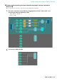
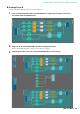
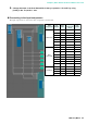
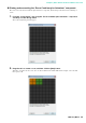
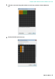

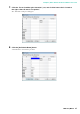

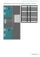
Table Of Contents
- Cover
- Introduction
- Setup workflow
- Example 1) Ballroom where the Room Combiner can be used
- Example 2) Remote conferencing system that also uses Speech Privacy
- Using the Device Configuration Wizard to create your device setup
- Configuring the settings on the MRX
- Making EXT. I/O settings
- Connecting the equipment
- Powering-on the MRX
- Powering-on the amp
- Specifying the computer’s TCP/IP address
- Sending the Speech Privacy environmental sound
- Taking MTX-MRX Editor online
- Verifying that the settings were applied
- Example 3) A paging system using the PGM1
- Using the Device Configuration Wizard to create your device setup
- Specifying the MRX configuration
- Making EXT. I/O settings
- Connecting the equipment
- Powering-on the PoE-equipped gigabit network switch
- Specifying the MCP1’s UNIT ID
- Power-on equipment other than amps and powered speakers
- Power-on amps and powered speakers
- Specifying the computer’s TCP/IP address
- Taking MTX-MRX Editor online
- Verifying that the settings were applied
- Q&A
- Uninstalling the software (Removing the application)

Example 1) Ballroom where the Room Combiner can be used
MRX Setup Manual
30
Placing and connecting components from “Room Combiner plus Automixer”
to analog outputs
Here we will place and connect the necessary components from the “Room Combiner plus Automixer” to the analog
outputs.
1.
Place the components shown below by dragging them from the “Components” area
and dropping them into the Design sheet.
• “Fader” (2 CH)
• “PEQ” (MONO, 6 BAND) × 2
• “Speaker Processor” (1 Way) × 2
• “ANALOG OUT”
2.
Make the connections from the “Room Combiner plus Automixer” to the “ANALOG
OUT.”
3.
Double-click “ANALOG OUT.”
The “ANALOG OUT” component editor will appear.