
User Manual
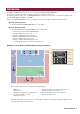

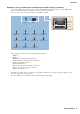
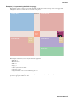


Table Of Contents
- Cover
- Introduction
- Setup workflow
- Example 1) Basic MTX3 system example (analog connections)
- Example 2) High audio quality system with XMV and YDIF connections (digital connections)
- Example 3) Using cascade mode to add MTX input channels (analog connection)
- Using the Device Configuration Wizard to create your device setup
- Making preliminary settings in MTX-MRX Editor
- Connecting the equipment
- Powering-on the MTX
- Powering-on the amp
- Setting the MCP1’s UNIT ID
- Specifying the computer’s TCP/IP address
- Taking MTX-MRX Editor online
- Making XMV settings
- Verifying that the settings were applied
- Example 4) A system using Dante
- Using the Device Configuration Wizard to create your device setup
- Making preliminary settings in MTX-MRX Editor
- Dante settings between systems
- Connecting the equipment
- Powering-on the MTX
- Powering-on the amp
- Specifying the computer’s TCP/IP address
- Taking MTX-MRX Editor online
- Making XMV settings
- Verifying that the settings were applied
- Example 5) A system using the PGM1 for paging
- Using the Device Configuration Wizard to create your device setup
- Making preliminary settings in MTX-MRX Editor
- Connecting the equipment
- Power-on the PoE-equipped gigabit network switch
- Power-on equipment other than amps and powered speakers
- Power-on amps and powered speakers
- Specifying the computer’s TCP/IP address
- Taking MTX-MRX Editor online
- Making XMV settings
- Verifying that the settings were applied
- Q&A
- Uninstalling the software (Removing the application)

Introduction
MTX Setup Manual
4
Example 3) Using cascade mode to add MTX input channels (analog connection)
Cascade mode allows the matrix buses to be shared between MTX units. This mode lets you use two MTX units to
increase the number of inputs, and output the combined inputs to a single amp.
In cascade mode, audio cannot be transmitted to the XMV via YDIF.
This example assumes that you’re using the following equipment.
•MTX3 × 2
•MCP1 × 1
• XMV4280 (or an amp with analog input) × 1
• Background music source such as a CD player × 1
• Speakers (the number needed)
• PoE network switch × 1
• Microphone with switch (for the MC or chair) × 1
• Wireless microphone receivers (11 channels)
• Wireless microphones × 11
The number of speakers is not specified; choose amps that are suitable for your speaker setup. You will also need to
provide the appropriate number of cables.
In order to supply power to the MCP1, the network switch must support PoE.
W/L Mic 1
Ch1 (MTX ID=01)
W/L Mic 5
Ch1 (MTX ID=02)
W/L Mic 9
Ch5 (MTX ID=01)
W/L Mic 2
Ch2 (MTX ID=01)
W/L Mic 6
Ch2 (MTX ID=02)
W/L Mic 10
Ch6 (MTX ID=01)
W/L Mic 3
Ch3 (MTX ID=01)
W/L Mic 7
Ch3 (MTX ID=02)
W/L Mic 11
Ch7 (MTX ID=01)
W/L Mic 4
Ch4 (MTX ID=01)
W/L Mic 8
Ch4 (MTX ID=02)
MCP1
ID=90
Rack
Microphone
Ch8 (MTX ID=01)
MTX3 ID=01
MTX3 ID=02
CD Player
XMV4280 ID
=1A
Room
Wireless Microphone
Receivers